



When does thermal system optimization for electronics reduce failure risk?




When does thermal system optimization for electronics reduce failure risk?
For electronics teams, heat is rarely a theoretical concern. The practical question is narrower: at what point does thermal system optimization for electronics stop being a nice engineering refinement and start becoming a reliability control measure?
That point usually arrives when thermal behavior begins to compress operating margin. In other words, failure risk rises when components spend too much time near their temperature limits, when local hotspots diverge sharply from the average board temperature, or when cooling performance varies enough with dust loading, altitude, enclosure layout, or workload that the system no longer behaves predictably. Under those conditions, thermal optimization is not just about lowering temperature. It is about stabilizing temperature distribution, slowing wear-out mechanisms, and keeping performance inside a known envelope.
This matters across industries. A control cabinet in a food plant, a power conversion module in industrial automation, a telecom edge unit, a battery management controller, or a semiconductor tool subassembly may all face the same underlying issue: rising power density with less tolerance for thermal drift. The details differ, but the failure logic is familiar.
The thermal threshold is not one number
It is tempting to ask for a single trigger temperature, but reliability engineers know that thermal risk rarely begins at one universal threshold. Most electronics failures are tied to the relationship between junction temperature, temperature cycling, thermal gradients, and time. A board can pass a bench test while still accumulating damage in field conditions because repeated cycling expands and contracts solder joints, package interfaces, connectors, and substrates.
So when does optimization start to reduce failure risk in a measurable way? Usually when one or more of these conditions appear:
- Peak component temperatures approach manufacturer derating limits or leave too little headroom for seasonal or workload variation.
- Temperature spread across critical components becomes large enough to create uneven aging or timing drift.
- Fan, heat sink, or enclosure performance degrades significantly with contamination, filter loading, or reduced airflow.
- The product experiences repeated on-off or load-following cycles that amplify thermo-mechanical stress.
- Field reliability depends on stable sensing, conversion efficiency, RF behavior, or control accuracy, all of which can shift with temperature.
In those situations, even modest thermal improvements can reduce failure probability because they change the stress profile, not just the absolute reading on one sensor.
Where failures actually begin
Not every warm system is at high risk. The real warning signs are concentrated heat and unstable heat flow.
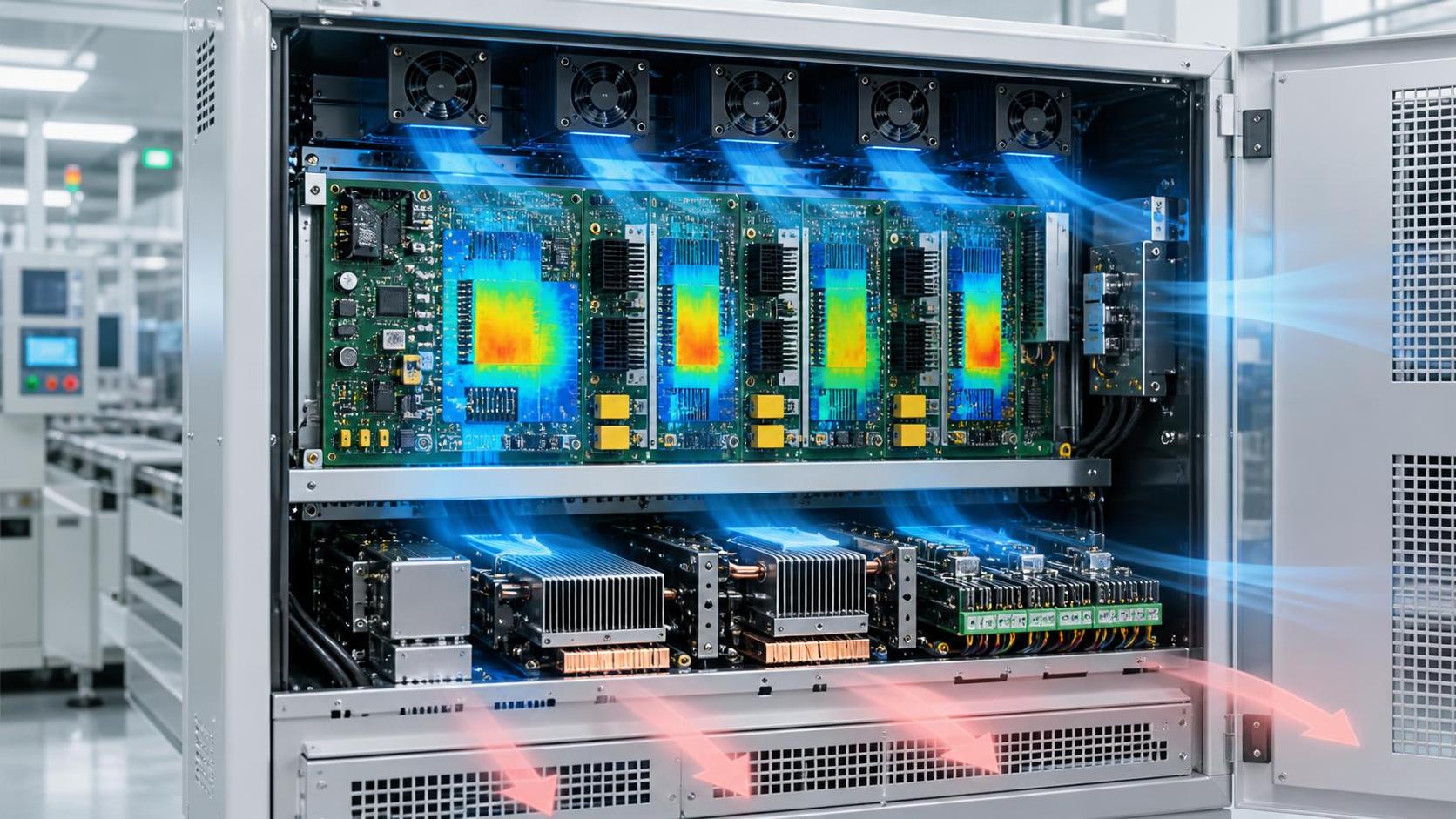
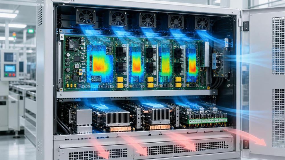
Power semiconductors, CPUs, GPUs, FPGAs, LED drivers, DC-DC converters, memory modules, and high-current connectors often fail first not because the average enclosure temperature is excessive, but because local heat removal is uneven. A board-level thermocouple may suggest acceptable conditions while the junction-to-case path, thermal interface material, or neighboring component placement creates a much higher hotspot.
This is why thermal system optimization for electronics often pays off most in dense assemblies. Once heat sources begin to interact, small design choices matter: the direction of airflow, the distance between tall components, copper plane continuity, vent placement, impedance to recirculation, and whether the fan curve still works after filter aging. A hotspot that is reduced by only a few degrees may still matter if it removes the component from a steep reliability cliff or cuts the depth of thermal cycling.
Standards and qualification methods can help frame the issue, but they do not replace application-specific analysis. Teams often look to IPC guidance, JEDEC thermal characterization methods, environmental test practices, or component derating rules. Those are useful anchors. Still, the key judgment is whether the actual operating profile matches the assumptions behind qualification.
Optimization has the strongest effect when margin is variable, not just low
A system running constantly at a known, controlled temperature can be easier to manage than a system with moderate average temperature but wide fluctuation. Many field failures emerge from variability: a cabinet door left closed in summer, a fan partially obstructed during maintenance, an installation at higher altitude where air density changes convective cooling, or a duty cycle that shifts after a software update.
Thermal optimization reduces failure risk most clearly when it makes the system less sensitive to those variations. That may involve:
- improving heat spreading so one overloaded component does not dominate the board temperature map,
- redesigning airflow paths to avoid short-circuit recirculation,
- selecting thermal interface materials that maintain contact quality over time,
- using fan control logic that reacts to the right sensor location rather than a lagging average,
- or separating sensitive analog, power, and heat-generating zones more effectively.
The gain here is not always dramatic in a brochure sense. More often, it shows up as fewer nuisance trips, less drift, slower capacitor aging, better solder joint survival, and fewer intermittent faults that are difficult to reproduce in the lab.
What technical evaluators should verify before approving changes
Thermal upgrades are easy to oversell and easy to misjudge. A larger heat sink, a faster fan, or a new enclosure layout may improve one metric while creating another problem such as noise, dust ingress, power consumption, vibration, or uneven cooling downstream. That is why evaluation should stay tied to failure mechanisms.
If those checks are skipped, thermal optimization can turn into cosmetic redesign rather than risk reduction.
Not all components respond equally to lower temperature
One common mistake is assuming every degree of cooling creates the same reliability benefit everywhere in the system. It does not. Electrolytic capacitors, certain power devices, optical elements, batteries, and some adhesives or polymers may show strong sensitivity to sustained high temperature. Other parts are less sensitive to steady-state temperature but more vulnerable to cycling amplitude or gradient. Connectors and solder joints, for example, often care as much about repeated expansion mismatch as about absolute temperature.
That means the most effective optimization target may not be the hottest visible part. It may be the component whose failure mode is most accelerated by the current thermal profile. In practice, technical evaluators should ask two questions together: which element runs hottest, and which element sets the system reliability limit?
The wider industrial context also matters
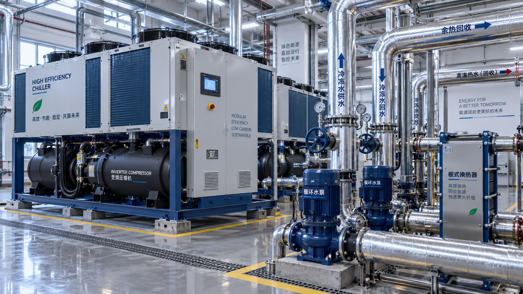
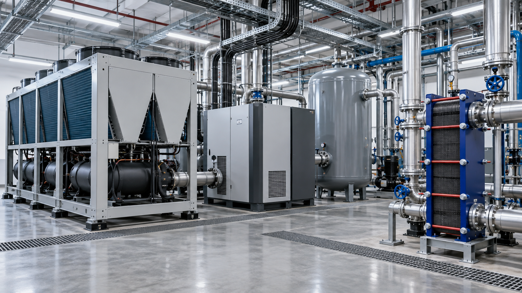
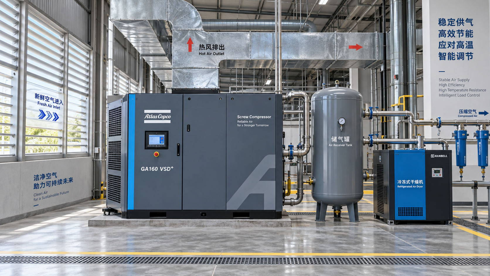
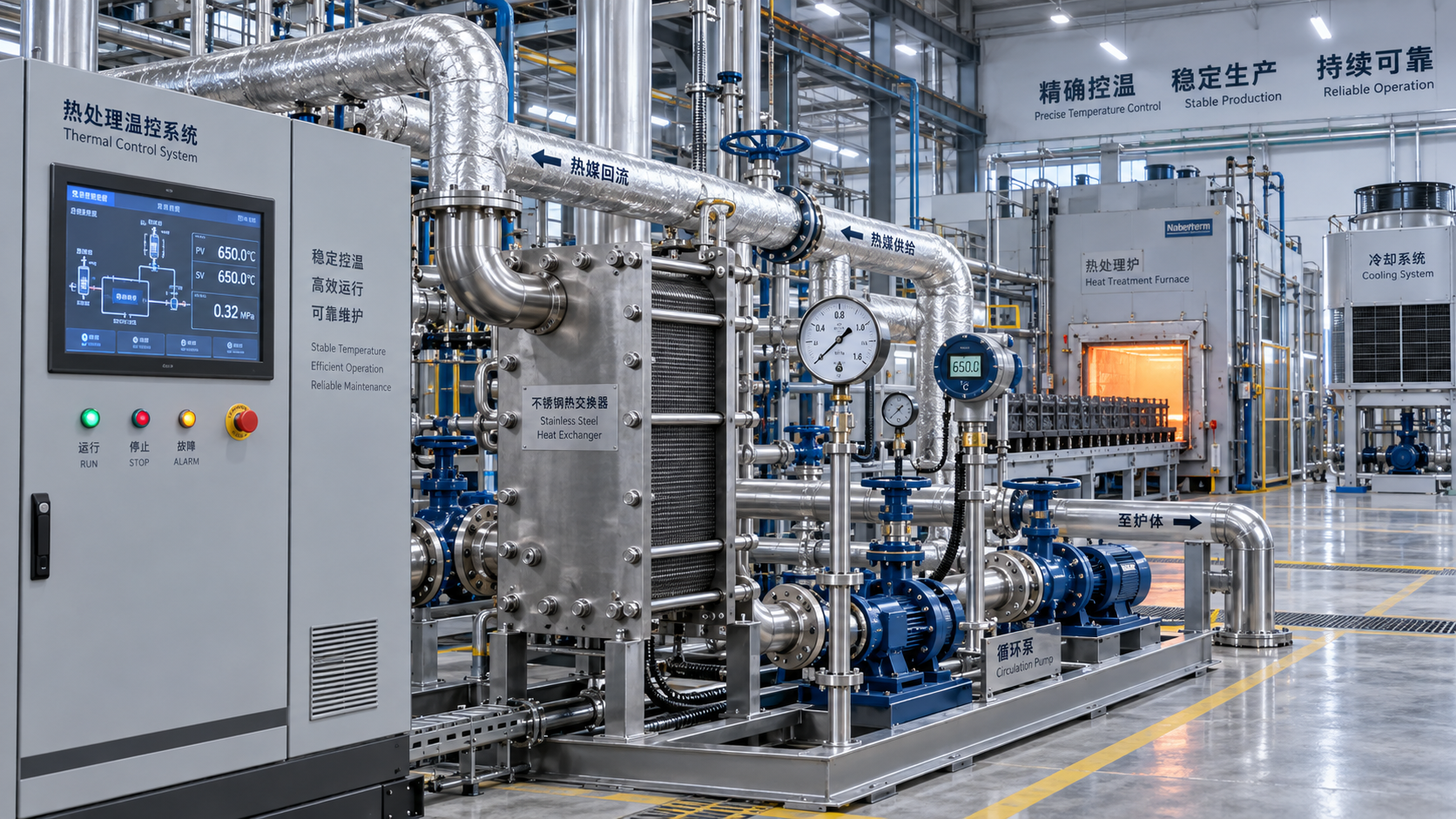
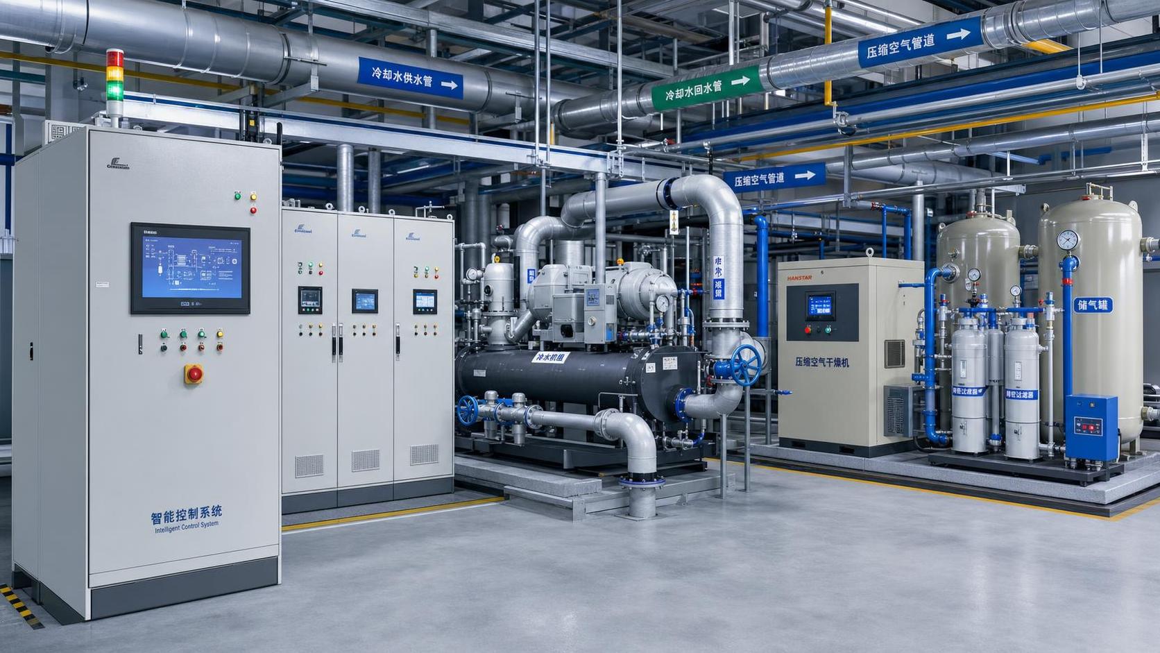
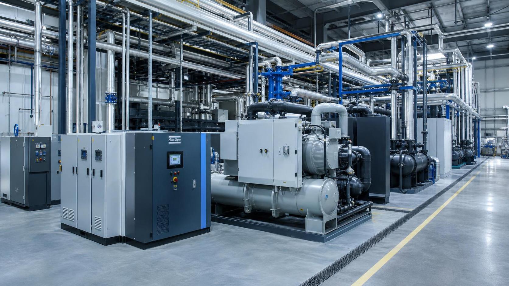
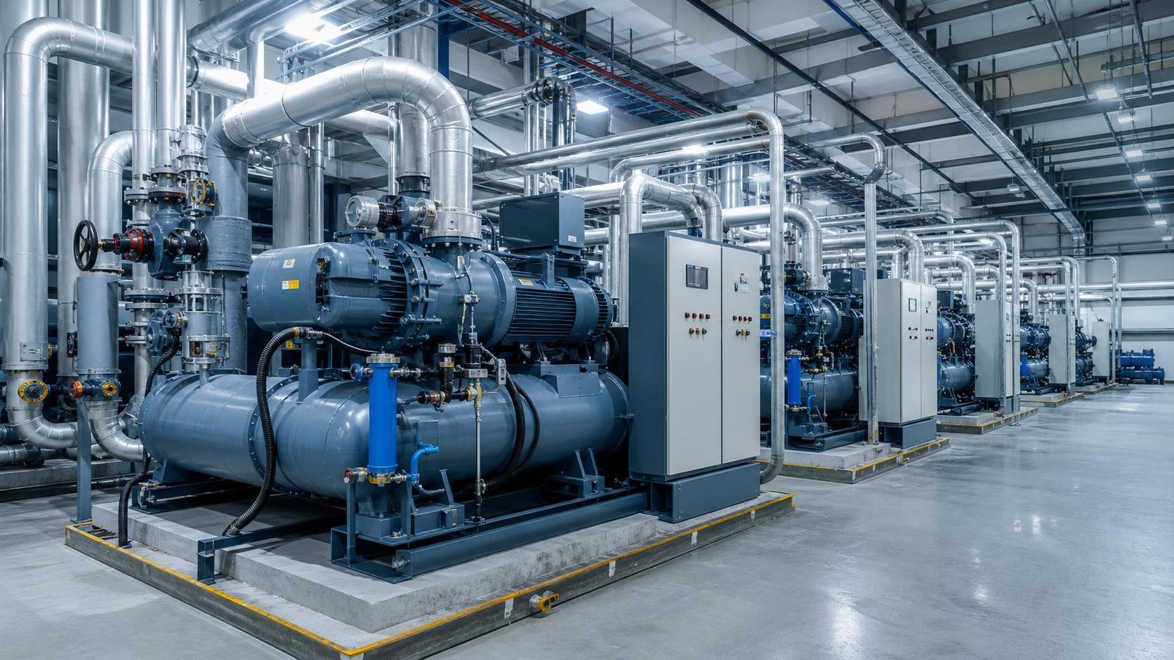
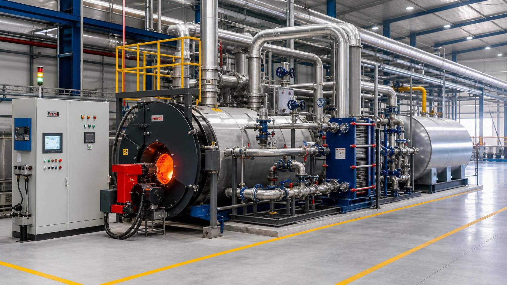
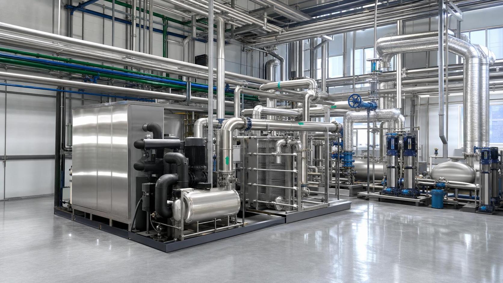
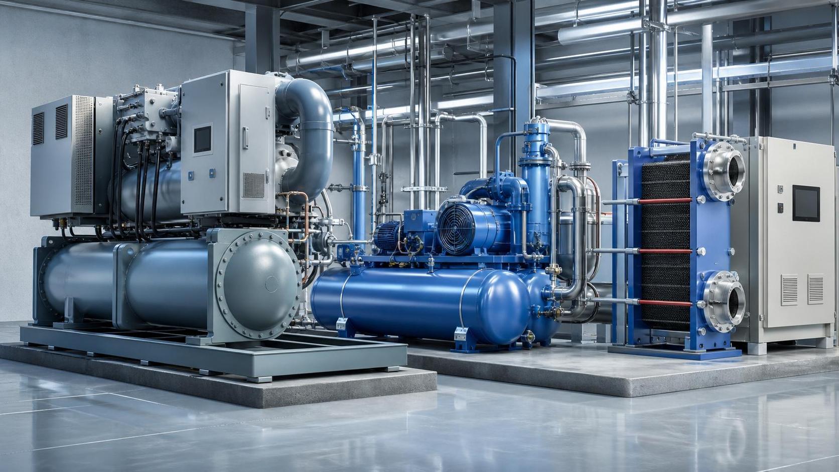
Electronics thermal design does not exist in isolation from the larger thermal infrastructure around it. Cooling air quality, compressed air availability for cabinet conditioning, heat exchanger selection, plant ambient conditions, and energy efficiency targets all shape the final result. In sectors like pharmaceuticals, semiconductors, and food processing, tighter process windows often push control electronics into environments where temperature stability matters as much as ruggedness.
This is one reason platforms such as GTC-Matrix have become useful to engineering and evaluation teams. The value is not just in tracking cooling hardware trends. It is in connecting board-level thermal concerns to broader developments in industrial cooling, compressed air, vacuum processes, and heat exchange technologies. A decision about enclosure cooling, for example, may be affected by energy pricing, refrigerant policy shifts, oil-free compression trends, or the availability of more efficient microchannel heat exchange approaches in the surrounding system architecture.
That broader view helps prevent narrow decisions. A local electronics fix may work in the lab yet conflict with plant energy priorities, maintenance practices, or contamination control requirements. Good evaluation bridges those layers instead of treating them separately.
When optimization is probably worth the effort
Thermal system optimization for electronics is usually justified when at least one of the following is true: the product is entering a higher power-density revision, field conditions are broader than qualification conditions, service access is limited, downtime cost is high, or the system already shows intermittent thermal alarms, drift, or unexplained resets. It is also worth closer attention when cooling performance depends heavily on consumables or maintenance discipline, because real-world upkeep is rarely ideal.
By contrast, if thermal headroom is already strong, hotspot distribution is well controlled, and failure analysis points elsewhere, extensive redesign may produce little practical benefit. Not every reliability problem is thermal, and not every warm product needs a new cooling strategy.
The best next step is usually not a full redesign. It is a disciplined review of temperature margin, hotspot location, cycling severity, and environmental variability against the actual failure mechanisms that matter in the application. Once those are clear, optimization choices become more obvious: improve spreading, improve airflow, reduce source power, separate thermal zones, or upgrade the surrounding cooling architecture.
If the goal is to reduce failure risk rather than simply lower reported temperature, the answer is straightforward: optimize when heat is no longer stable, localized, or predictable enough to preserve margin over the product’s real operating life. That is the point where thermal engineering stops being incremental and becomes decisive.
Related News
- What drives sustainable thermal systems cost over their operating life?Author :

- Which industrial solution comparison criteria prevent project delays?Author :

- How Ambient Temperature and Load Profile Affect Industrial Compressor SizingAuthor :

- What to evaluate before choosing a thermal process engineering supplierAuthor :

- How industrial utility systems affect energy costs in process plantsAuthor :

- What Data Is Needed to Assess Heat Recovery Decarbonization?Author :

- Can Waste Heat Recovery Support Carbon Neutrality Targets?Author :

- Is Compressor Heat Recovery Worth the Installation Cost?Author :

- What to verify before choosing a process separation technology supplierAuthor :

- When does process utilities engineering reduce project rework?Author :

- Where thermal efficiency optimization delivers the fastest savings in EuropeAuthor :

- What should you verify before selecting a heat transfer supplier?Author :

- What drives compressed air systems price for industrial projects?Author :

- How an industrial product knowledge comparison guide reduces sourcing riskAuthor :

- When does a procurement specification planning process reduce bid risk?Author :

- When does thermal system optimization for electronics reduce failure risk?Author :

- When high temperature process heating systems justify the higher energy costAuthor :

- How to compare sludge dewatering equipment by cake drynessAuthor :

- What to Check Before Sourcing a Gas Turbine for Distributed Power ProjectsAuthor :

- What drives industrial thermal systems price in large facility projectsAuthor :

- How to build an industrial product comparison chart that speeds up vendor selectionAuthor :

- Vacuum Technology Application Guide for Selecting the Right SystemAuthor :

- What Drives Vacuum Drying Cost in Industrial Procurement?Author :

- What Drives Compressed Air Pricing in Industrial Systems?Author :

- How Procurement Specification Planning Shapes Total Project CostAuthor :

- Compression Technology Guide: How to Compare Efficiency, Pressure Range, and Maintenance NeedsAuthor :

- How to Compare Industrial Separators by Throughput, Purity, and Maintenance LoadAuthor :

- How to Size a Compressed Air Equipment Receiver Tank for Stable PressureAuthor :

- Industrial Equipment Selection Guide: How to Compare Capacity, Duty Cycle, and Operating CostAuthor :

- How to Evaluate an Intellectualization Supplier for Industrial UpgradesAuthor :

- High-Efficiency Manufacturing: Cost Savings vs. Upgrade RiskAuthor :

- Thermal System Optimization Cost: What Drives ROI?Author :

- How to Plan Process Utilities for a Cleanroom Without Costly ReworkAuthor :

- How to Compare Process Heating Suppliers in MexicoAuthor :

- Food Processing Utilities: Common Sizing Mistakes That Raise Energy and Water UseAuthor :

- How to Build Procurement Specification Planning for Industrial EquipmentAuthor :