



Which vacuum specification best protects semiconductor process yield?




The vacuum specification that best protects semiconductor process yield is the one that keeps the process chamber clean and pressure-stable throughout the actual recipe, not the one with the lowest published ultimate pressure. For many semiconductor tools, particle contribution, hydrocarbon backstreaming, pumping-speed stability across the operating-pressure range, gas compatibility, and recovery after venting or process byproducts have a more direct relationship with wafer contamination than the pump's base-pressure figure alone.
A vacuum source is part of the process environment. It affects how quickly reactive gases leave the chamber, whether condensable species remain near the wafer, how consistently pressure-control hardware behaves, and whether contamination can travel from the foreline back toward the process volume. A pump selected only from a nominal pressure target can meet a datasheet requirement while creating intermittent defects that are difficult to trace.
Start with the operating pressure, not the ultimate pressure
Ultimate pressure describes the lowest pressure a pump may reach under controlled conditions, often with a clean, dry system and little or no gas load. Semiconductor process chambers rarely operate in that condition. Deposition, etch, implantation support, load-lock cycling, degas steps, and chamber cleaning each impose different gas loads and pressure ranges.
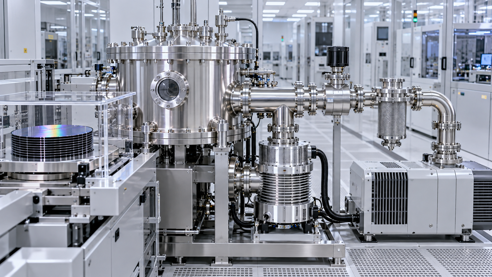
The relevant question is whether the pumping system supplies adequate effective pumping speed at the chamber during the pressure range used by the recipe. This is lower than the pump's catalog pumping speed because conductance losses occur in the chamber outlet, gate valve, foreline, traps, elbows, reducers, and particulate filters. A long narrow line can dominate system performance, particularly in molecular-flow conditions. Increasing pump capacity at the far end of a restrictive foreline may produce little improvement at the chamber.
Pressure control also deserves separate review. A system can have sufficient average capacity yet exhibit pressure oscillation when a throttle valve, pressure controller, and pump response do not work well together. In plasma etch and deposition, unstable chamber pressure can alter residence time, plasma density, ion energy distribution, film uniformity, or etch profile. The pressure trace during gas transitions and plasma ignition is often more informative than a static pressure reading.
Use the right speed curve
Request pumping-speed curves across the intended pressure window and for gas mixtures that resemble the process load. Nominal speed expressed for nitrogen does not automatically represent performance with hydrogen, helium, water vapor, fluorinated gases, or heavier precursor fragments. Gas species affect compression ratio, heat generation, discharge behavior, and the response of downstream abatement equipment.
For cyclic tools, examine transient behavior as carefully as steady-state behavior. A load lock may require repeatable pump-down after each wafer transfer. A process chamber may need rapid removal of residual gas before the next step. Slow or variable recovery can increase cycle time, but the more serious concern is incomplete removal of reactive or condensable residues before a sensitive process begins.
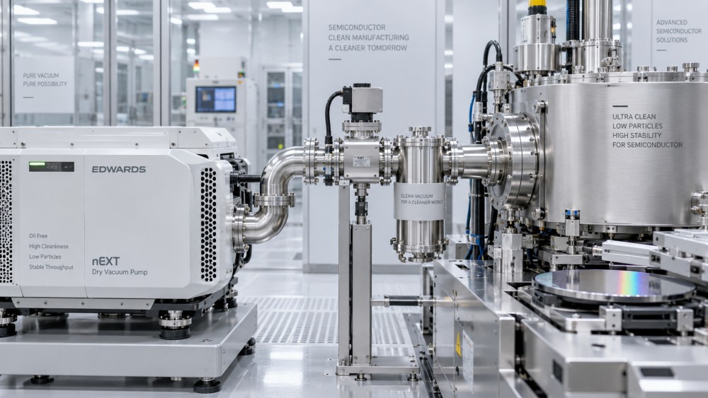
Particle control is often the yield-protection specification
Particles are not a single failure mode. They may originate from worn pump internals, seal degradation, powder accumulation in the foreline, flaking deposits, valve wear, or material released during maintenance. Their size, composition, mobility, and route back to the chamber determine their significance. A vacuum pump can be mechanically reliable while still being unsuitable for a particle-sensitive process because its internal materials or exhaust path shed contamination under thermal cycling.
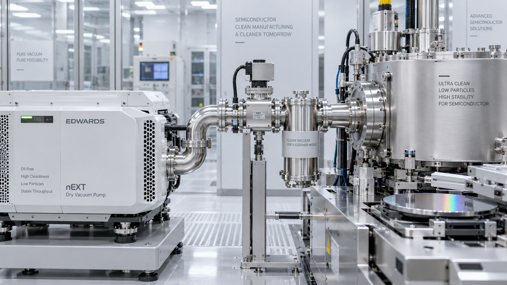
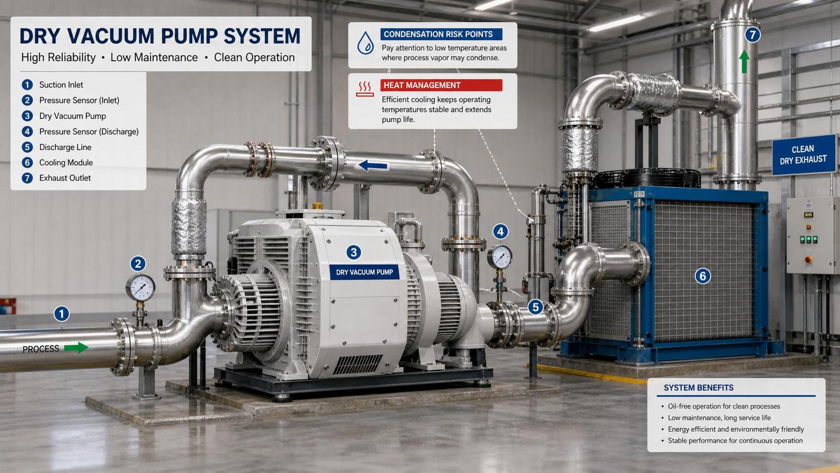
Dry vacuum pumps are often preferred where oil contamination is unacceptable, but “dry” should not be treated as a complete cleanliness claim. Dry-running designs still require assessment of internal coatings, rotor clearances, purge arrangements, bearing isolation, and the behavior of process deposits. A pump handling abrasive or polymer-forming byproducts may gradually lose clearance or accumulate material that later releases as particles during a pressure excursion.
The foreline is part of the particle-control system. Horizontal sections, dead legs, abrupt expansions, and poorly supported flexible connections can collect process residue. A later pressure pulse, valve event, or vibration can mobilize that material. Components placed between the chamber and pump need low-shedding construction, appropriate cleaning, and a geometry that avoids stagnant pockets. Filters can retain debris, yet an incorrectly selected filter can become a pressure-drop source or a reservoir that releases accumulated material during service.
For processes with tight particle limits, the specification should define more than a generic “clean vacuum” expectation. It should address acceptable materials of construction, process-side cleanliness requirements, isolation methods during regeneration or maintenance, and the conditions under which particle performance is verified. Inspection should include the installed foreline assembly rather than only the pump delivered from the factory.
Hydrocarbon-free performance needs a system-level definition
Hydrocarbon contamination can interfere with thin-film adhesion, alter surface energy, raise background signals in analytical tools, and create difficult-to-explain defects at interfaces. The contamination source may be lubricating oil, seal compounds, assembly lubricants, elastomer outgassing, contaminated purge gas, or maintenance materials. A low-hydrocarbon specification therefore cannot be satisfied by choosing an oil-free pump alone.
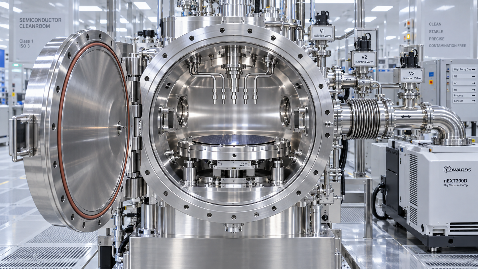
Where process sensitivity is high, evaluate the complete path from chamber to exhaust. This includes valve-seat materials, O-rings, gauges, pressure-control devices, backing lines, and any shared vacuum header. A shared header introduces a cross-contamination pathway when tools run dissimilar chemistries or when one line experiences an upset. Isolation valves, correct purge sequencing, and a review of flow direction during shutdown are more useful controls than a broad assurance that the pump is clean.
Backstreaming risk changes with pressure, temperature, and operating state. It is most often discussed in connection with lubricated pumps, but the broader issue is reverse transport of vapors or residues from downstream equipment. During power loss, pump stop, venting, or an improperly controlled pressure equalization event, gases can move in directions that do not occur during normal production. Anti-suckback features, isolation logic, and vent gas purity should be examined as process-protection requirements rather than convenience features.
Gas compatibility determines whether performance remains stable
Semiconductor vacuum duty can be chemically aggressive even when the chamber pressure is moderate. Halogen-containing etch gases, fluorinated cleaning chemistry, metal-organic precursors, dopant sources, water vapor, and reaction byproducts impose different requirements on wetted materials and temperature management. The important evaluation is not merely whether a pump can tolerate a named gas; it is whether it can maintain stable operation with the actual mixture, flow profile, purge scheme, and duty cycle.
Corrosive gases can attack metals, elastomers, coatings, and sensor components. Condensable gases may deposit in cooler parts of the foreline or inside the pump. Powder-producing chemistry can accumulate where velocity falls or surface temperature changes. Each mechanism can produce a different field symptom: rising base pressure, declining pumping speed, erratic motor load, valve sticking, increased particle counts, or an exhaust restriction. Treating all of these symptoms as simple pump wear delays the correct response.
Temperature control is closely tied to chemical compatibility. A pump running too cool may allow deposition of condensable byproducts. A pump running too hot can accelerate chemical attack, change deposit morphology, or challenge seals and purge performance. The specified temperature range should match the intended chemistry and the expected facility conditions. Ambient temperature, cooling-water stability, cabinet airflow, and exhaust backpressure all influence the internal thermal state.
Inert purge flow needs the same disciplined review. It can dilute reactive gases, reduce deposition, and protect critical clearances, but excessive purge changes the gas throughput seen by the pump and exhaust system. Insufficient purge can allow deposits or corrosion to develop in locations that are not visible during routine external inspection. Purge quality also matters; contaminated nitrogen can introduce moisture or hydrocarbons into a system intended to protect clean surfaces.
Compression ratio and forepump behavior matter near the process boundary
In systems using a high-vacuum pump with a mechanical backing pump, the combined specification matters. The high-vacuum stage may provide excellent performance only when foreline pressure remains within its allowable range. A backing pump that is undersized, chemically degraded, or restricted by downstream equipment can raise forepressure and reduce compression of light gases. The chamber may then show a higher partial pressure of species that are particularly difficult to remove.
Light gases deserve attention because their behavior can differ sharply from heavier process gases. Hydrogen and helium, for example, place different demands on compression and leak assessment. A total-pressure gauge may appear acceptable while residual-gas composition remains unsuitable for a sensitive step. Where the process is vulnerable to a specific background species, partial-pressure measurement or residual-gas analysis provides a more relevant acceptance signal than total pressure alone.
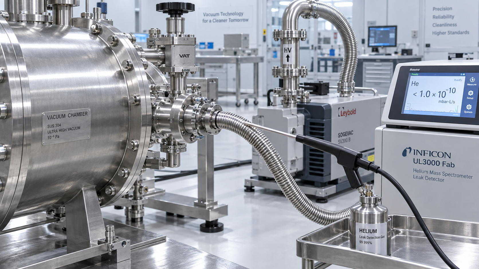
Do not interpret a slow pump-down automatically as inadequate pump capacity. A real leak, virtual leak, trapped moisture, desorption from chamber surfaces, a saturated trap, a clogged foreline component, or a failing valve can create similar curves. The slope and repeatability of the pump-down trace help separate these causes. A leak often persists with a characteristic pressure behavior, while desorption and moisture effects tend to improve after controlled bakeout, drying, or repeated cycling. Replacing the pump without resolving the actual source can repeat the problem.
Specify recovery after interruption and maintenance
Yield exposure frequently occurs at transitions: after a chamber opening, a pump change, an abnormal vent, a power interruption, or a prolonged idle period. A suitable vacuum specification should define how the system isolates the chamber, how it is vented, what gas is used, and what conditions must be restored before process material is introduced.
Rapid pump-down is useful only when it does not pull loose contamination toward the chamber or force process residue through components not designed for the flow direction. Controlled venting with clean, dry gas reduces moisture ingress, while correct isolation prevents reverse flow from an inactive backing line. After service, replacement components require cleanliness control, compatible seals, torque practices that do not damage fittings, and removal of packaging debris before the system is opened to the chamber.
Acceptance criteria should include repeatability across several representative cycles, rather than a single successful pump-down. Observe base pressure, time to pressure stabilization, throttle-valve behavior, leak response, motor load, cooling conditions, and any change in particle or background-gas indicators. The purpose is to reveal drift and transient instability that a one-time performance test can miss.
A practical specification hierarchy
When the process is highly contamination-sensitive, rank vacuum requirements in the order that reflects yield exposure: chamber-side cleanliness and particle behavior first; chemical compatibility and deposit management next; stable effective pumping speed at operating pressure; controlled recovery after abnormal states; then ultimate pressure as a confirmation that the system has sufficient margin. This order changes for a less sensitive utility vacuum application, but it is appropriate where the vacuum line forms part of the wafer environment.
The final pump selection should be based on the installed system configuration: chamber volume, recipe pressures, gas flows, process chemistry, line conductance, valve sequence, abatement backpressure, cooling conditions, and maintenance interval. A published pump specification remains useful, but only after it has been connected to those conditions. That connection is what turns a vacuum rating into a yield-protection requirement.
Related News
- Which vacuum specification best protects semiconductor process yield?Author :Vacuum Process Fellow

- How Can Contamination Be Prevented in a Semiconductor Vacuum Chamber?Author :Vacuum Process Fellow

- Which Vacuum Pump Specifications Matter Most for Semiconductor Processes?Author :Vacuum Process Fellow

- How to find leaks in vacuum pump systems before pump performance dropsAuthor :Vacuum Process Fellow

- How to size a Roots blower for vacuum process equipmentAuthor :Vacuum Process Fellow

- How vacuum level affects vacuum process efficiencyAuthor :Vacuum Process Fellow

- China Imposes Temporary Helium Export BanAuthor :Vacuum Process Fellow

- Semiconductor Vacuum Systems Factory Checklist for Process Stability and Cleanroom UseAuthor :Vacuum Process Fellow

- Vacuum Process Optimization Services: Signs Your Line Needs a Performance ReviewAuthor :Vacuum Process Fellow

- Vacuum Chambers for Cleanroom Use: Key Design Points That Prevent ContaminationAuthor :Vacuum Process Fellow

- Vacuum Distillation Systems: Key Performance Metrics That Affect Product PurityAuthor :Vacuum Process Fellow

- Vietnam Halts High Vacuum Pump Import Licenses for 30 DaysAuthor :Vacuum Process Fellow

- Vacuum Technology Database: What to Check Before Using Technical DataAuthor :Vacuum Process Fellow

- Dry Pump Vacuum System Design Mistakes That Raise DowntimeAuthor :Vacuum Process Fellow

- When Vacuum Systems Lose Performance: Common Causes and FixesAuthor :Vacuum Process Fellow
![]()
- EU Tightens EN 13445-3 Weld Testing for Vacuum VesselsAuthor :Vacuum Process Fellow
![]()
- EPA Cuts R-1234ze(E) Quota 35%, Tightening Vacuum Cooling SupplyAuthor :Vacuum Process Fellow
 Quota 35%, Tightening Vacuum Cooling Supply")
- ICA Warns of Tight Copper Alloy Supply for Vacuum PumpsAuthor :Vacuum Process Fellow

- Vacuum System Leak Detection: Signs, Tests, and FixesAuthor :Vacuum Process Fellow

- How to Compare Vacuum Systems Factory Capabilities for Stable Process UptimeAuthor :Vacuum Process Fellow

- Vacuum Pump Lead Times Extend to 26 WeeksAuthor :Vacuum Process Fellow

- Semiconductor Vacuum Systems Explained for Stable Process YieldAuthor :Vacuum Process Fellow

- Vacuum Process Efficiency: 7 Hidden Causes of Energy LossAuthor :Vacuum Process Fellow

- Vacuum Technology Solutions for Stable Low-Pressure ProductionAuthor :Vacuum Process Fellow

- Vacuum Processes: Common Efficiency Losses and FixesAuthor :Vacuum Process Fellow

- Common Vacuum Processes Problems and How to Prevent DowntimeAuthor :Vacuum Process Fellow

- Tantalum Spike Extends Vacuum Crucible Lead TimesAuthor :Vacuum Process Fellow

- Vacuum Process Efficiency: 5 Hidden Losses to Check FirstAuthor :Vacuum Process Fellow

- How Heat Transfer Design Impacts Vacuum Process EfficiencyAuthor :Vacuum Process Fellow

- EN 13445-4:2026 Takes Effect for High-Vacuum ComponentsAuthor :Vacuum Process Fellow

- EU Vacuum Components Face New EN 13445-4:2026 Leak Test RuleAuthor :Vacuum Process Fellow

- UBS: Fed Cut View May Ease Vacuum Pump Lead TimesAuthor :Vacuum Process Fellow

- Vacuum Processes: Common Causes of Unstable PerformanceAuthor :Vacuum Process Fellow
![]()
- SiC Certification Signals New Entry Path for Vacuum and Compressor DrivesAuthor :Vacuum Process Fellow
![]()
- How to Choose the Right Vacuum System for Process StabilityAuthor :Vacuum Process Fellow

- Vacuum Technology Selection: What Matters Most for Stable Process PerformanceAuthor :Vacuum Process Fellow