



How to size vacuum process equipment for the required pump-down time




A vacuum system is correctly sized only when it reaches the required pressure within the required time under the gas load that exists in production—not merely when its nominal pumping speed appears large enough on a datasheet. Chamber volume matters, but it is only the starting point. Leakage, material outgassing, process gas admission, internal conductance, vapor handling, and the pressure range all determine whether a selected system can repeat the intended cycle.
The most useful early distinction is between an empty-chamber pump-down calculation and a process-duty calculation. The first estimates how quickly a clean, sealed volume can fall from one pressure to another. The second determines whether the complete vacuum process equipment can maintain that performance after fixtures, products, hot surfaces, gas evolution, contamination, and operating variation are included. Purchase decisions should be based on the second.
Define the pressure-time requirement before selecting a pump
A pump-down specification needs more precision than “reach vacuum in five minutes.” At minimum, establish:
- Effective internal volume, including chamber, connected piping, valves, manifolds, and permanently installed tooling;
- Initial pressure at the beginning of evacuation, which may be atmospheric pressure or a controlled backfill pressure;
- Target pressure at the point where the process can start, rather than the lowest pressure a pump can theoretically achieve;
- Required pump-down time, including or excluding valve transitions, roughing, stabilization, and interlock delays;
- Gas composition and expected gas release from the load;
- Permitted pressure variation during the process step;
- Cycle frequency and expected operating temperature.
The target pressure deserves special attention. A drying process may need a specified absolute pressure to lower a liquid’s boiling point. A coating or plasma process may require a stable operating-pressure window after pump-down. A leak test may require low pressure only long enough to produce a valid measurement. These conditions lead to different equipment selections even when the chamber volume is identical.
Pressure units must also be consistent throughout the calculation. Mixing mbar, Pa, Torr, and microns is a routine source of major sizing errors. Absolute pressure, not gauge pressure, is required for vacuum calculations.
The ideal calculation is a screening tool, not the final answer
For an evacuated, rigid volume with no gas load and constant effective pumping speed, the approximate pump-down time is:
t = (V / Seff) × ln(P1 / P2)
where t is time, V is chamber volume, Seff is the effective pumping speed at the chamber, P1 is initial absolute pressure, and P2 is final absolute pressure.
If volume is expressed in cubic metres and pumping speed in cubic metres per hour, the calculated time is in hours. In practice, it is often clearer to use litres and litres per second, yielding seconds.
Consider a 1,000 L chamber that must move from 1,000 mbar to 10 mbar. If the effective pumping speed at the chamber were truly 100 L/s throughout the pressure range, the ideal estimate would be:
t = (1,000 / 100) × ln(1,000 / 10) ≈ 46 seconds
That result does not mean a 100 L/s pump will deliver a 46-second production cycle. It assumes a clean, empty chamber; no pipe losses; no pressure-dependent pump behavior; no desorption from surfaces; no load moisture; and no valve or control delay. Its value is comparative: it shows the approximate scale of pumping capacity needed and exposes unrealistic schedule assumptions early.
The equation also shows why the last decade of pressure reduction is frequently more difficult than expected. Reducing pressure from 1,000 to 100 mbar and from 100 to 10 mbar requires the same ideal evacuation time at constant pumping speed. In real systems, the second interval is often slower because gas evolution becomes more important while conductance and pump performance may deteriorate.
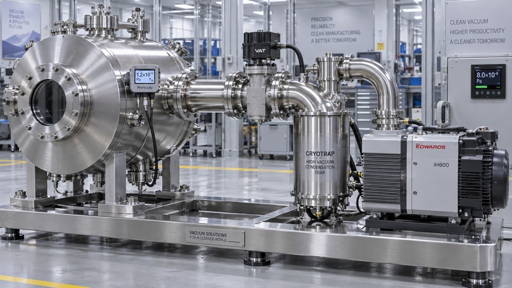
Use effective pumping speed at the chamber, not catalogue displacement
The pump nameplate may show a displacement or nominal pumping speed at the inlet. The chamber experiences a lower value after piping, elbows, valves, filters, traps, separators, and internal restrictions are included. This is the effective pumping speed:
1 / Seff = 1 / Spump + 1 / C
Here, C is the conductance of the line between chamber and pump. The relationship is important because a high-capacity pump cannot compensate indefinitely for a poorly designed connection. If line conductance is much lower than pump speed, the line—not the pump—sets the attainable pump-down rate.
Conductance is highly pressure-dependent. In viscous flow at higher pressures, restrictions behave differently from molecular flow at lower pressures. At deeper vacuum, long narrow pipes, sharp elbows, undersized valves, and restrictive inlet components can have a disproportionately severe impact. A layout acceptable for rough vacuum may be unsuitable for high-vacuum duty.
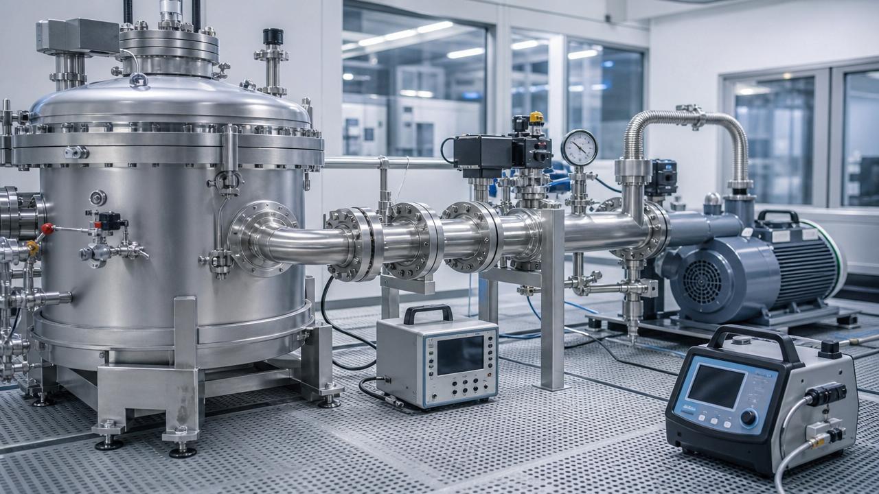
For preliminary evaluation, minimize the distance between chamber and pump, use the largest practical line diameter, avoid unnecessary elbows, and verify the flow path through every valve and accessory. The relevant question is not whether a DN connection matches the pump inlet; it is whether the complete path provides sufficient conductance at the required pressure range.
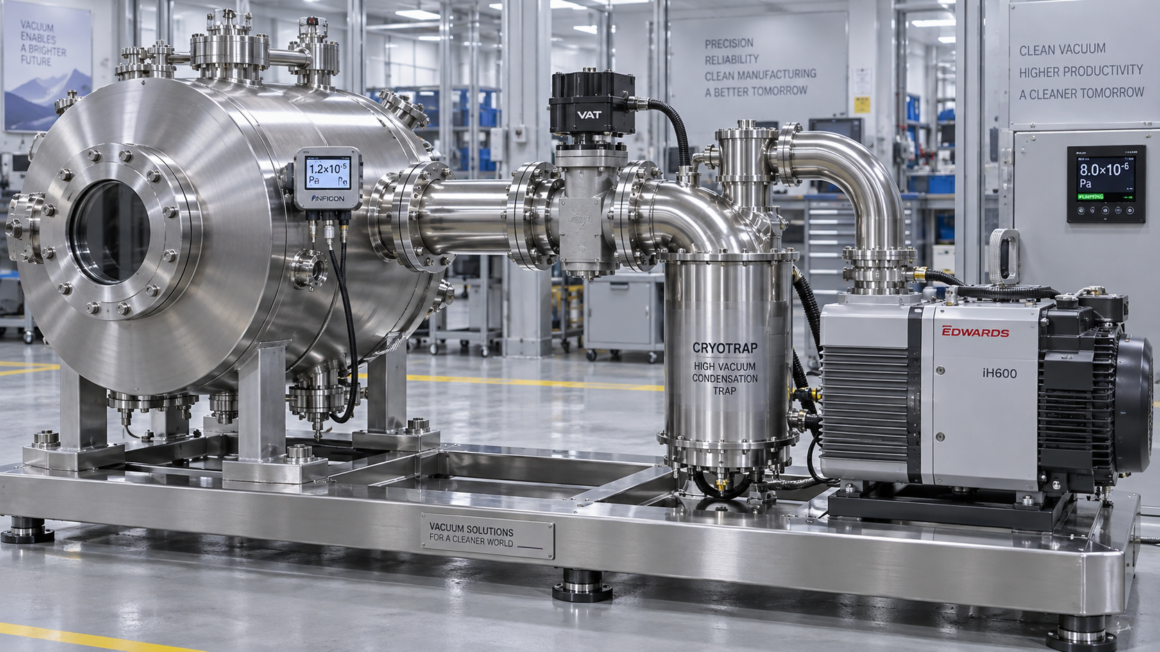
A common specification error is to request a pump based on chamber volume while allowing the equipment supplier to define piping later. For time-critical vacuum process equipment, the chamber connection, isolation valve, foreline geometry, condensate handling, and instrumentation layout should be treated as part of the performance boundary.
Gas load determines whether the calculated endpoint is achievable
Once chamber pressure has fallen, the pump is no longer removing only the original air inventory. It must continuously handle gas entering or emerging from the system. The steady-state pressure is approximately:
P = Q / Seff
where Q is total gas load in pressure-volume flow units, such as mbar·L/s, and Seff is effective pumping speed at the chamber.
Total gas load may include real leaks, virtual leaks, outgassing, intentional process gas flow, evaporation, permeation through elastomer seals, and backstreaming or internal contamination. This is why ultimate pressure published for an isolated pump is rarely the correct basis for system selection.
Leaks and virtual leaks are not the same problem
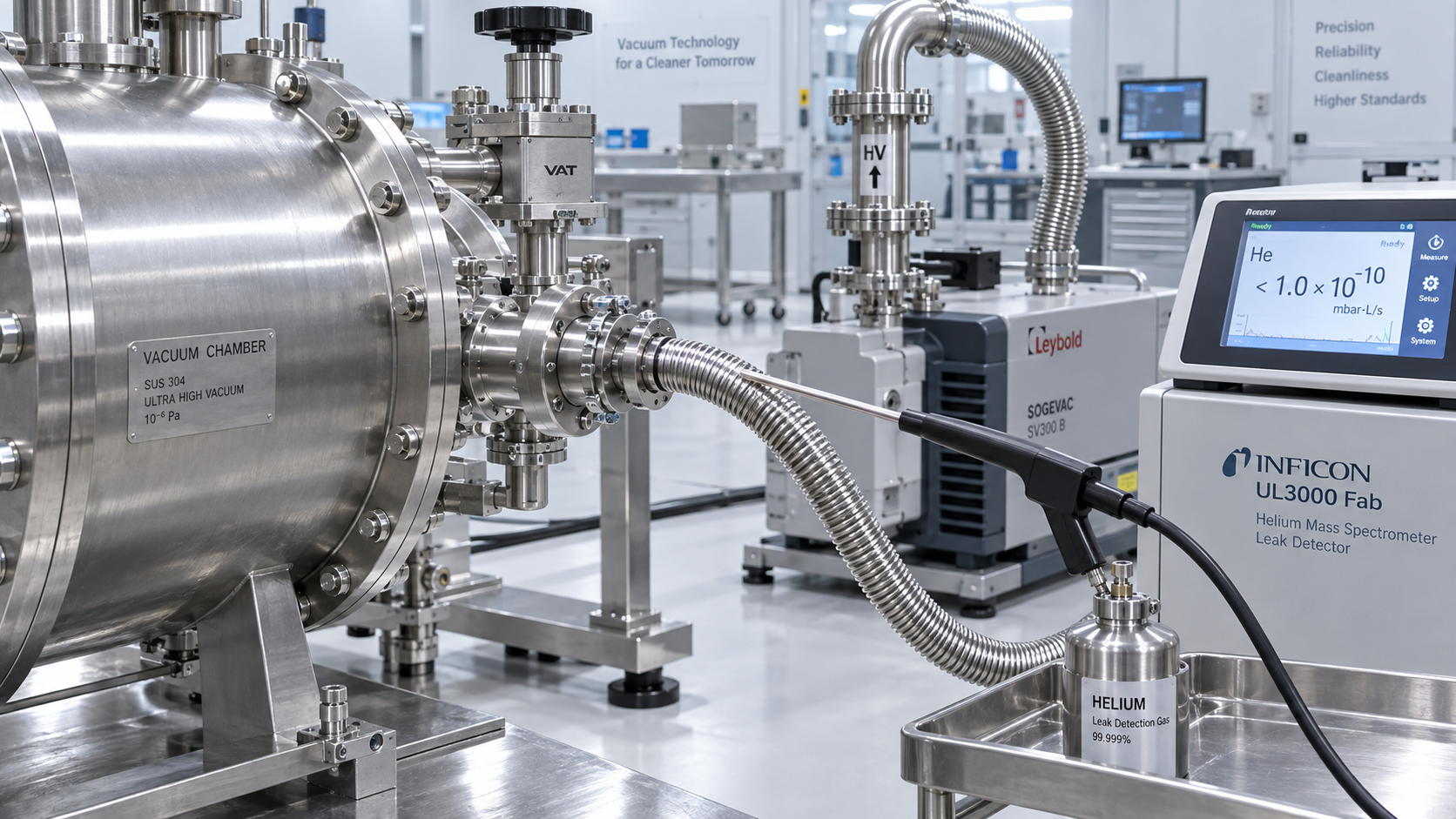
A real leak admits external gas through an imperfect seal, weld, fitting, feedthrough, damaged O-ring, or porous component. It may be intermittent and can become more visible as the system cools, heats, or moves.
A virtual leak is trapped gas escaping slowly from a confined volume. Blind threaded holes, overlapping plates, poorly vented screw cavities, unvented bellows spaces, and crevices behind fixtures can all create this effect. Increasing pump size may shorten early roughing but often does little to remove a persistent pressure tail caused by trapped volumes. The corrective action is design modification: vented hardware, simplified geometry, appropriate sealing, and cleaning.
Outgassing often controls the late stage of pump-down
Water vapor adsorbed on internal surfaces is a frequent source of slow pump-down, particularly after chambers are opened to ambient air. Polymers, lubricants, adhesives, porous materials, elastomer seals, and product residues can add substantial and variable gas load. Heated loads may release vapors that are insignificant at room temperature but dominant during operation.
A system intended for repeatable cycle time should therefore be sized around the actual surface condition and load state. A large metal chamber with clean, dry, low-vapor fixtures can evacuate predictably. A smaller chamber containing wet parts, warm porous product, or solvent residue can demand more robust pumping, vapor management, and stabilization time.
Surface preparation and operating discipline may improve cycle performance more economically than selecting a substantially larger pump. Bakeout, dry-gas venting, controlled loading, material restrictions, and planned cleaning are engineering controls, not merely maintenance preferences.
Separate roughing, crossover, and high-vacuum duty
Many systems cannot be accurately represented by one constant pumping speed. Mechanical oil-sealed rotary vane pumps, dry screw pumps, claw pumps, liquid-ring pumps, Roots boosters, turbomolecular pumps, cryogenic pumps, and diffusion pumps operate most effectively in different pressure ranges and gas conditions.
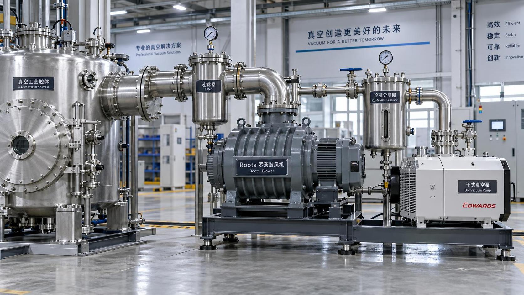
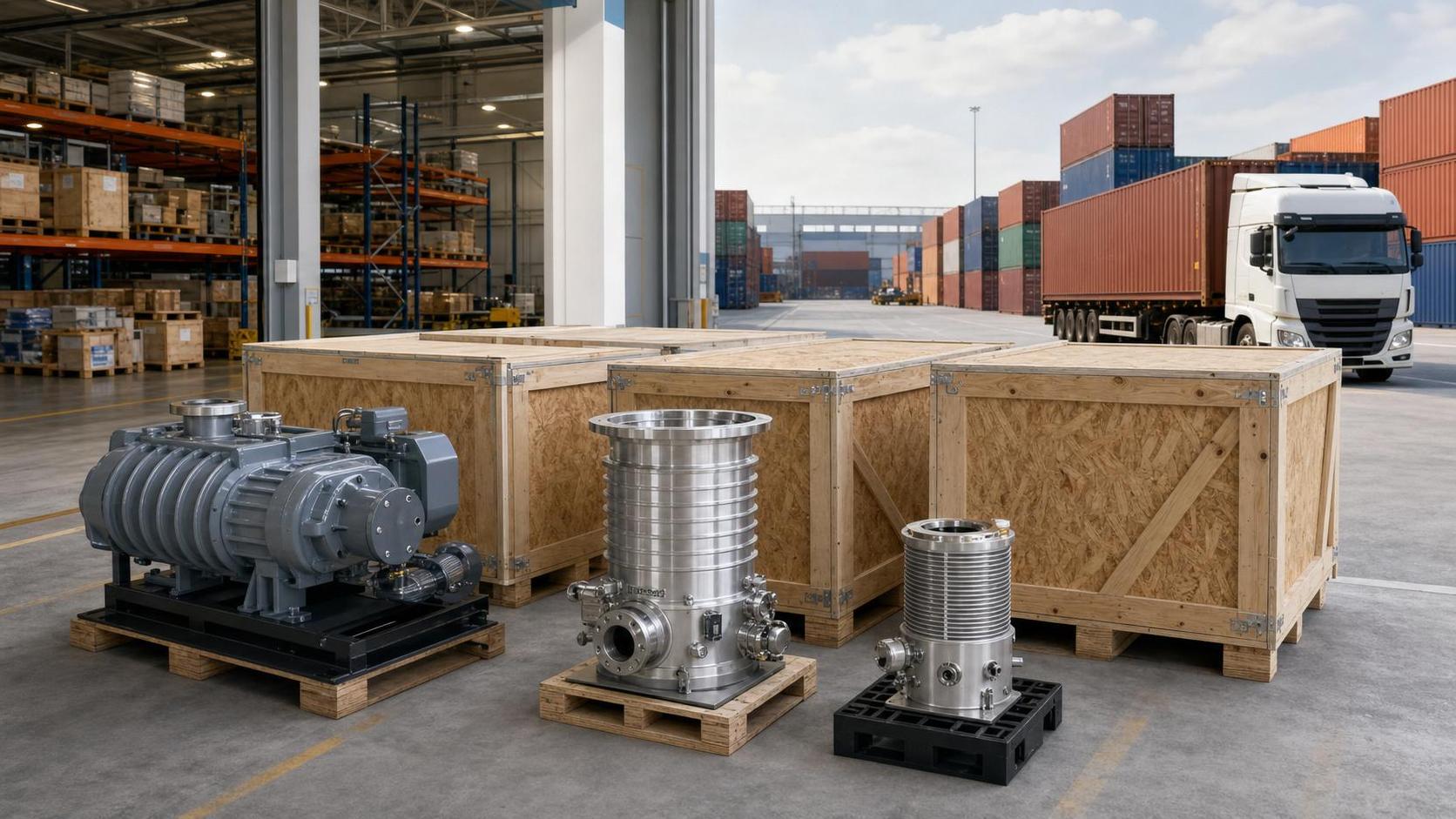
A roughing pump may provide adequate capacity near atmospheric pressure but become inefficient for the required endpoint. A Roots blower can significantly reduce pump-down time over part of the rough-vacuum region, but it generally needs controlled crossover and backing support. A turbomolecular pump can achieve low pressure with clean compatible gases, yet its forepump, inlet conductance, particulate exposure, and vapor load need separate assessment.
The calculation should therefore be divided into pressure bands. For each band, determine the available pumping speed at the chamber, expected gas load, operating limits, and transition logic. This approach is more accurate than averaging all pump speeds into a single number.
It also exposes a critical choice: whether the requirement is genuinely for deeper vacuum or simply for faster roughing. Overspecifying a high-vacuum stage to solve a roughing-time problem can increase capital cost, control complexity, and maintenance burden without improving the controlling portion of the cycle.
Check vapor handling before adding pumping speed
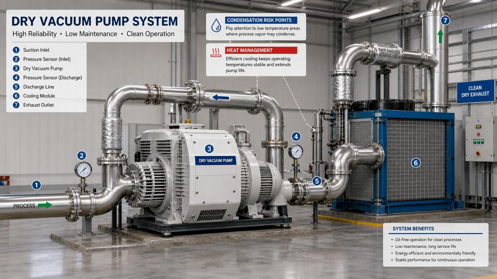
Water, solvents, oils, monomers, and process by-products alter both pump selection and sizing. A pump can have sufficient nominal gas throughput while still being unsuitable for the vapor load. Condensation in forelines, dilution of pump oil, corrosion, deposits, seal incompatibility, and unstable ultimate pressure can follow.
Relevant questions include the vapor pressure at process temperature, maximum evaporation rate, whether vapor reaches the pump as gas or condenses upstream, and whether condensable species are compatible with pump internals and exhaust treatment. Gas ballast may help an oil-sealed pump tolerate some condensable vapor, but it reduces achievable vacuum and can increase energy use. It is not a universal answer to heavy vapor service.
Cold traps, condensers, knockout vessels, heated lines, dry pumps, and staged pumping may be justified when vapor load dominates. Each changes the pressure drop and operating behavior of the system, so the protection equipment must be included in the effective-speed model rather than treated as an afterthought.
Account for process variability and control margins
A nominal pump-down time should not be used as an acceptance criterion without defining the starting condition. Door-open duration, humidity during loading, product mass, fixture temperature, product moisture, cleaning method, and prior process exposure can all change the gas load. A design that meets the target only under dry, empty-chamber conditions may fail to provide a usable production margin.
The appropriate margin is not a fixed percentage. It should reflect uncertainty in the inputs and the consequence of missing the cycle-time requirement. A tightly controlled analytical chamber may have a well-characterized load. A chamber used for varied products, volatile materials, or frequent atmospheric exposure needs a broader design envelope and clearer operating limits.
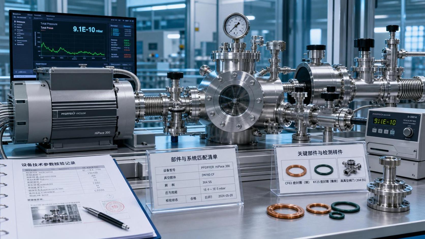
Instrumentation should support verification of those limits. A roughing gauge alone may not provide reliable indication across the complete range. Pirani, capacitance diaphragm, cold-cathode, and other gauges have different operating regions, gas dependencies, contamination sensitivities, and accuracy characteristics. Control setpoints should be based on a gauge appropriate to the pressure range and gas composition, particularly when the target pressure is close to the process threshold.
Evaluate energy and reliability in the same calculation
Meeting pump-down time with the largest available pump is seldom the most balanced solution. Oversized pumps may draw unnecessary power during long hold periods, increase heat rejection requirements, raise noise, and create excessive inlet velocities that disturb powder, product, or coatings. They can also mask chamber defects that later become expensive reliability problems.
Conversely, a system selected too close to its capacity limit may run continuously at high load, experience elevated operating temperature, or lose cycle consistency as pump condition changes. Variable-speed drives, staged pumps, automatic isolation, booster bypass control, and standby logic can reduce energy consumption while retaining peak capacity, but only if the process sequence is designed around real pressure and gas-load conditions.
Maintenance assumptions belong in the selection basis. Pump performance is affected by oil condition, seal wear, fouling, filter restriction, corrosion, and accumulated condensate. A robust specification should state the performance point after normal service exposure, not only at factory-clean condition.
A defensible sizing package
The final selection should be supported by more than a requested pump model and chamber volume. A usable technical package defines the pressure-time profile, chamber and line geometry, calculated conductance, anticipated gas-load sources, process-gas and vapor characteristics, pump curves by pressure range, crossover conditions, utility requirements, and control philosophy. It should also identify the acceptance test: loaded or unloaded chamber, initial condition, target pressure, elapsed time, allowable stabilization period, and gauge location.
This documentation prevents a recurring dispute in vacuum projects: a pump may meet its published performance at its own inlet while the installed system misses the required cycle at the chamber. By making the chamber-side pressure profile and real gas load the basis of selection, vacuum process equipment can be sized for repeatable operation rather than an optimistic calculation.
Related News
- How to size vacuum process equipment for the required pump-down timeAuthor :Vacuum Process Fellow

- Which vacuum specification best protects semiconductor process yield?Author :Vacuum Process Fellow

- How Can Contamination Be Prevented in a Semiconductor Vacuum Chamber?Author :Vacuum Process Fellow

- Which Vacuum Pump Specifications Matter Most for Semiconductor Processes?Author :Vacuum Process Fellow

- How to find leaks in vacuum pump systems before pump performance dropsAuthor :Vacuum Process Fellow

- How to size a Roots blower for vacuum process equipmentAuthor :Vacuum Process Fellow

- How vacuum level affects vacuum process efficiencyAuthor :Vacuum Process Fellow

- China Imposes Temporary Helium Export BanAuthor :Vacuum Process Fellow

- Semiconductor Vacuum Systems Factory Checklist for Process Stability and Cleanroom UseAuthor :Vacuum Process Fellow

- Vacuum Process Optimization Services: Signs Your Line Needs a Performance ReviewAuthor :Vacuum Process Fellow

- Vacuum Chambers for Cleanroom Use: Key Design Points That Prevent ContaminationAuthor :Vacuum Process Fellow

- Vacuum Distillation Systems: Key Performance Metrics That Affect Product PurityAuthor :Vacuum Process Fellow

- Vietnam Halts High Vacuum Pump Import Licenses for 30 DaysAuthor :Vacuum Process Fellow

- Vacuum Technology Database: What to Check Before Using Technical DataAuthor :Vacuum Process Fellow

- Dry Pump Vacuum System Design Mistakes That Raise DowntimeAuthor :Vacuum Process Fellow

- When Vacuum Systems Lose Performance: Common Causes and FixesAuthor :Vacuum Process Fellow
![]()
- EU Tightens EN 13445-3 Weld Testing for Vacuum VesselsAuthor :Vacuum Process Fellow
![]()
- EPA Cuts R-1234ze(E) Quota 35%, Tightening Vacuum Cooling SupplyAuthor :Vacuum Process Fellow
 Quota 35%, Tightening Vacuum Cooling Supply")
- ICA Warns of Tight Copper Alloy Supply for Vacuum PumpsAuthor :Vacuum Process Fellow

- Vacuum System Leak Detection: Signs, Tests, and FixesAuthor :Vacuum Process Fellow

- How to Compare Vacuum Systems Factory Capabilities for Stable Process UptimeAuthor :Vacuum Process Fellow

- Vacuum Pump Lead Times Extend to 26 WeeksAuthor :Vacuum Process Fellow

- Semiconductor Vacuum Systems Explained for Stable Process YieldAuthor :Vacuum Process Fellow

- Vacuum Process Efficiency: 7 Hidden Causes of Energy LossAuthor :Vacuum Process Fellow

- Vacuum Technology Solutions for Stable Low-Pressure ProductionAuthor :Vacuum Process Fellow

- Vacuum Processes: Common Efficiency Losses and FixesAuthor :Vacuum Process Fellow

- Common Vacuum Processes Problems and How to Prevent DowntimeAuthor :Vacuum Process Fellow

- Tantalum Spike Extends Vacuum Crucible Lead TimesAuthor :Vacuum Process Fellow

- Vacuum Process Efficiency: 5 Hidden Losses to Check FirstAuthor :Vacuum Process Fellow

- How Heat Transfer Design Impacts Vacuum Process EfficiencyAuthor :Vacuum Process Fellow

- EN 13445-4:2026 Takes Effect for High-Vacuum ComponentsAuthor :Vacuum Process Fellow

- EU Vacuum Components Face New EN 13445-4:2026 Leak Test RuleAuthor :Vacuum Process Fellow

- UBS: Fed Cut View May Ease Vacuum Pump Lead TimesAuthor :Vacuum Process Fellow

- Vacuum Processes: Common Causes of Unstable PerformanceAuthor :Vacuum Process Fellow
![]()
- SiC Certification Signals New Entry Path for Vacuum and Compressor DrivesAuthor :Vacuum Process Fellow
![]()
- How to Choose the Right Vacuum System for Process StabilityAuthor :Vacuum Process Fellow