


How to select vacuum process solutions for semiconductor etching




Selecting vacuum process solutions for semiconductor etching requires more than matching a pump to a target pressure. A system that performs well on a clean, steady gas load may struggle when exposed to reactive chemistry, condensable byproducts, frequent recipe changes, or demanding uptime requirements. For technical evaluators, the real task is to understand how the chamber, pressure-control hardware, pump, exhaust line, and abatement system behave together.
The right selection balances process stability with contamination control, serviceability, energy consumption, and total cost of ownership. It also leaves room for the recipes and production volumes a fab expects to run—not just the conditions described in an initial equipment quotation.
Start with the etch process, not the pump catalog
An etch chamber’s operating pressure is only one point in a much larger operating envelope. Before comparing vacuum technologies, assemble a process profile covering every relevant recipe step, including pumpdown, stabilization, etching, cleaning, purge, and idle. The most demanding condition may occur outside the main etch step, when a cleaning chemistry or temperature transition changes the exhaust composition.
Give suppliers a controlled specification that identifies the following:
- Pressure range and control requirements: Chamber setpoints, allowable variation, transition times, and any sensitivity to pressure disturbances.
- Gas loads: Species, flow rates, mixtures, sequencing, and expected changes during each step, including purge and clean gases.
- Reaction products: Known or suspected solids, condensable compounds, corrosive species, and materials that may form deposits downstream.
- Production pattern: Wafer throughput, recipe mix, chamber utilization, planned idle periods, and anticipated capacity changes.
- Site constraints: Available footprint, cooling water, electrical supply, nitrogen, exhaust capacity, safety controls, and maintenance access.
Some chemistry details may be confidential. Even so, the pump and abatement suppliers need enough information to assess compatibility and foreseeable failure modes. Use an appropriate confidentiality process rather than substituting a generic gas list for actual operating conditions.
Map the whole exhaust path
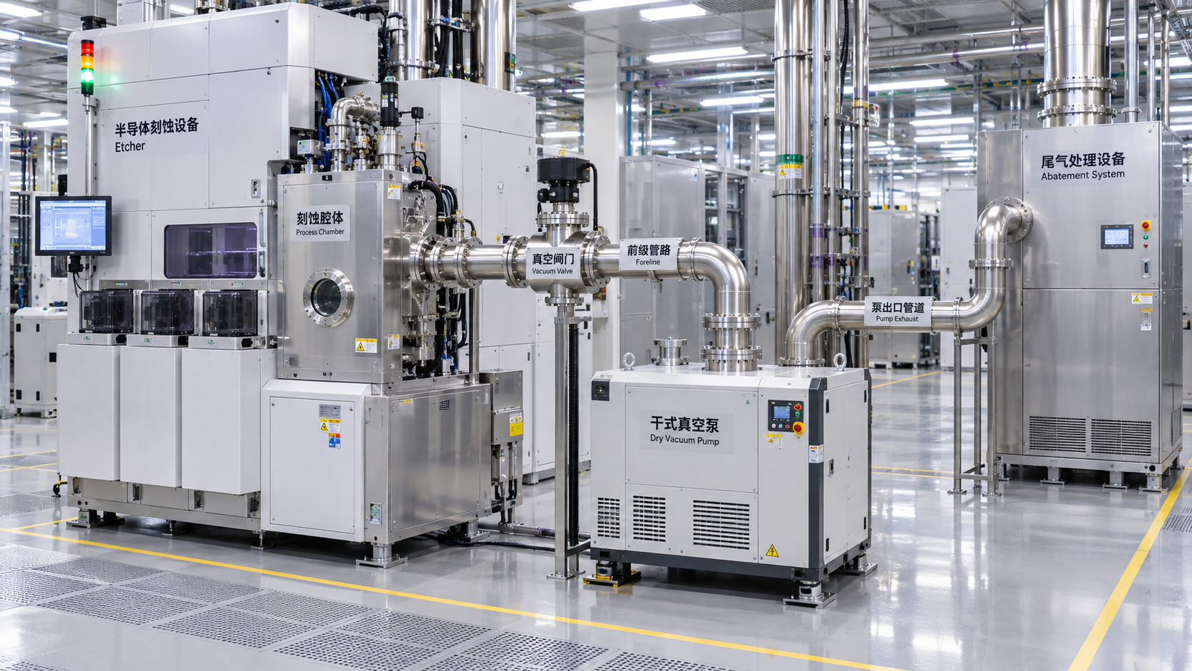
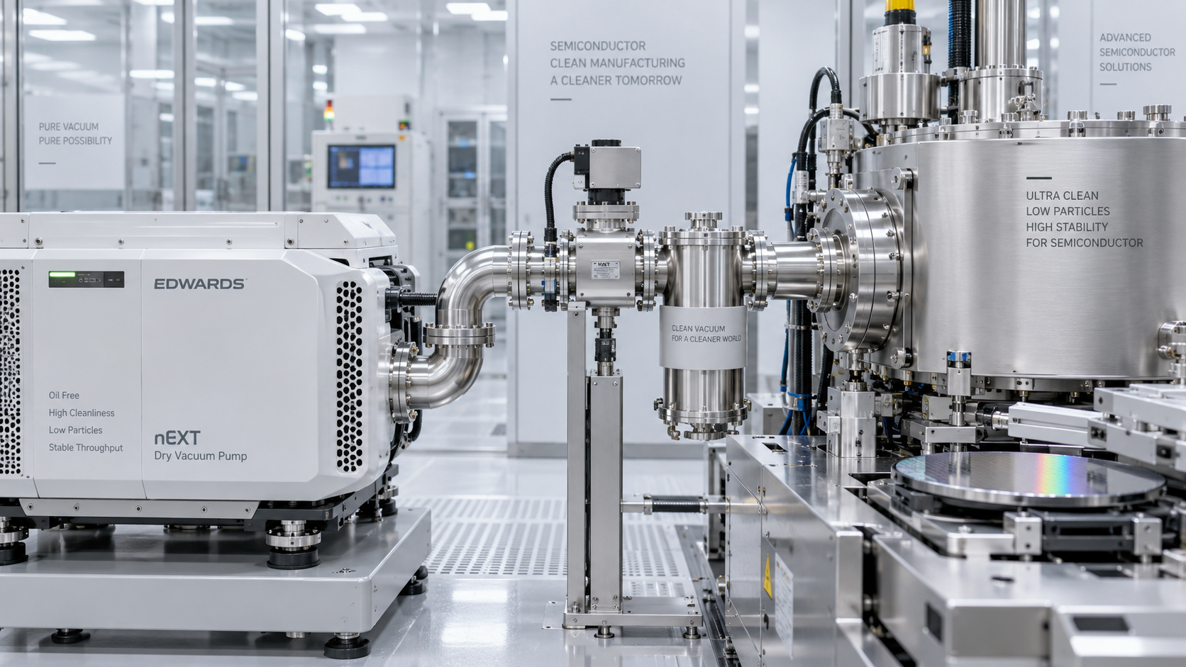
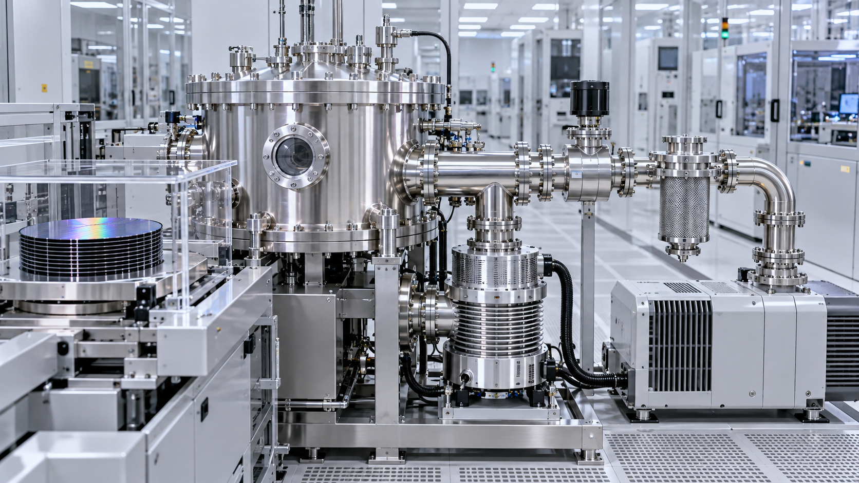
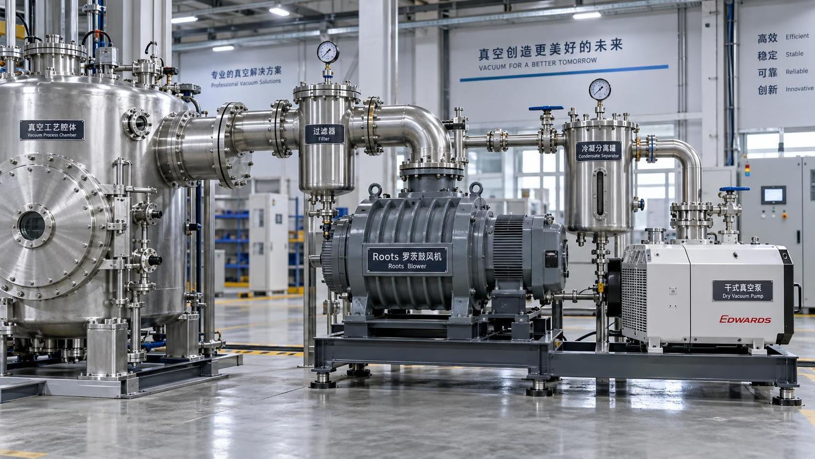
In semiconductor etching, the vacuum pump is part of a connected process system. Chamber pressure control, foreline conductance, pump performance, exhaust routing, and downstream abatement all influence one another. A restriction or deposit in one location can show up as an instability somewhere else.
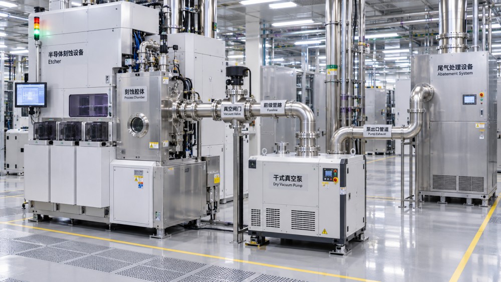
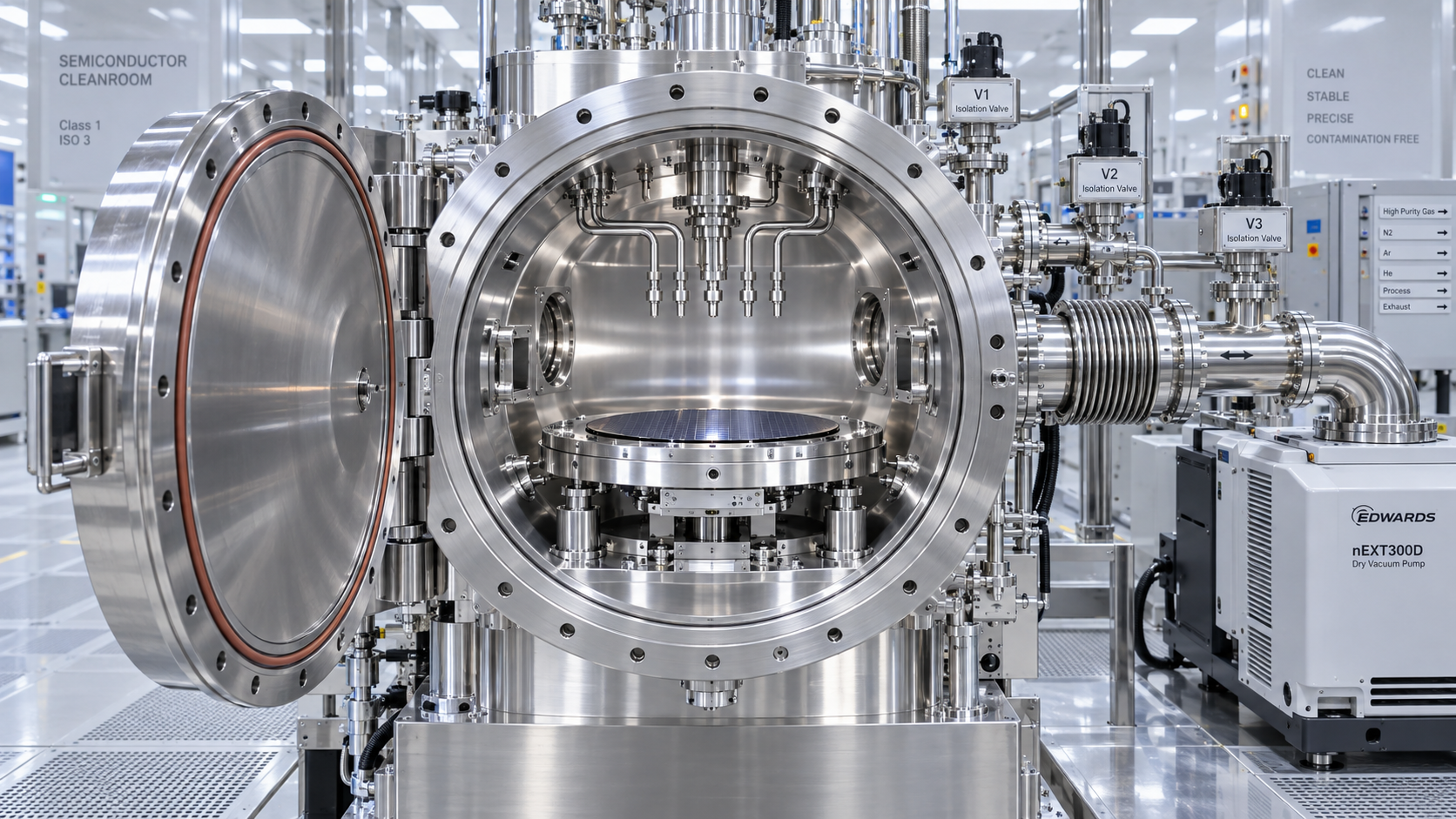
Trace the path from chamber to exhaust, noting valves, throttle controls, traps, heated sections, pumps, isolation points, and abatement connections. Review normal operation alongside startup, shutdown, purge, and fault conditions. The resulting diagram gives equipment, process, facilities, and environmental health and safety teams a common basis for discussion.
Pay particular attention to interfaces between suppliers. For example, determine who defines the acceptable pump exhaust pressure, who assesses the effect of abatement on that pressure, and who owns the response if the combined system falls outside the agreed operating window.
Compare vacuum technologies against the actual duty
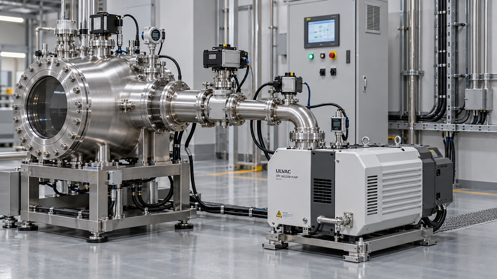
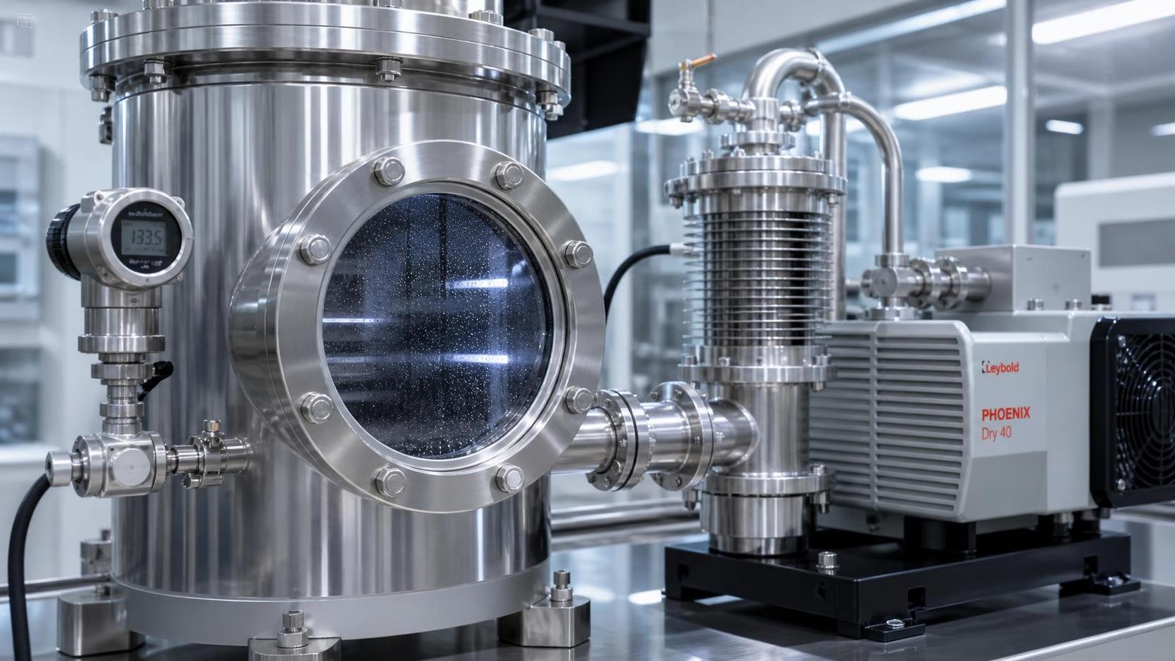
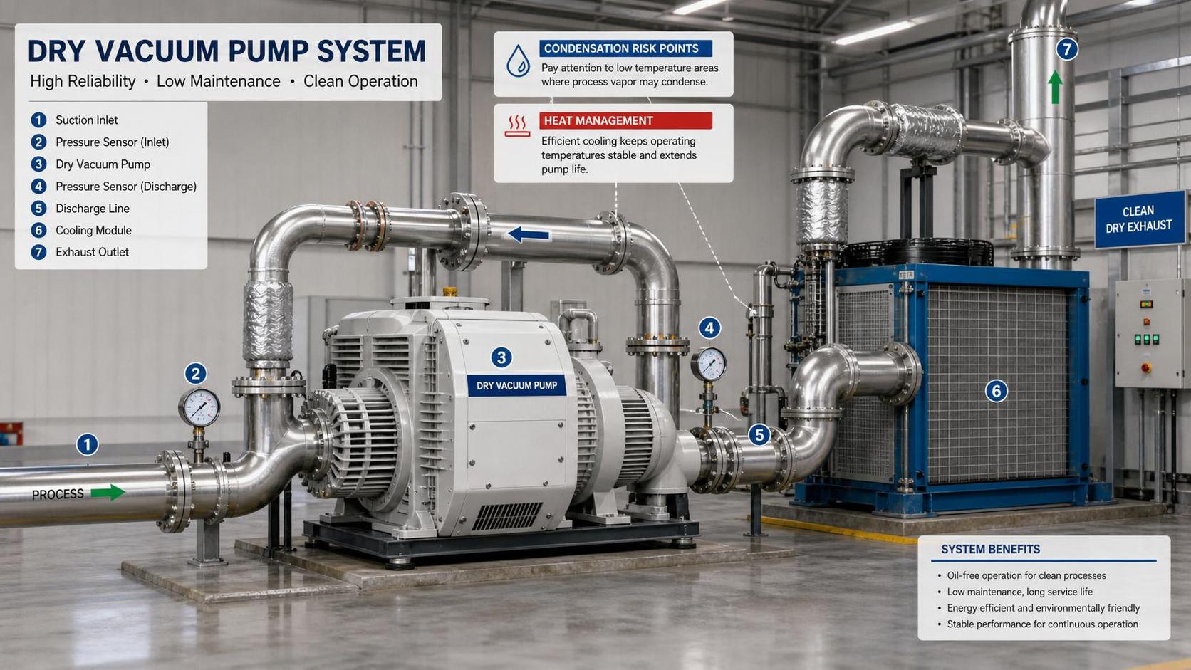
Dry vacuum pumps are widely considered for semiconductor etch applications because the process gas path does not rely on oil as the sealing fluid in the same way as an oil-sealed rotary vane pump. That can simplify hydrocarbon contamination control, but “dry” does not mean immune to corrosion, particle buildup, or all maintenance. Material selection, clearances, temperature management, and purge strategy remain important.
These categories are starting points, not universal rankings. Pumps within the same category can differ substantially in their coatings, purge arrangements, thermal design, controls, and tolerance of process byproducts. Request application-specific evidence rather than assuming a pump is suitable because it has been used somewhere in semiconductor manufacturing.
Read the speed curve at the chamber
Nominal pumping speed alone can be misleading. Ask for the speed curve across the relevant pressure range and evaluate the effective speed at the chamber after accounting for the foreline, valves, fittings, and other restrictions. Gas composition and operating temperature also matter; a published curve measured under reference conditions may not describe the installed system.
Work with the supplier to check whether the proposed configuration can handle peak gas loads and pressure transitions without sacrificing control at lower-flow steps. Oversizing is not automatically safer: it may add capital cost, utilities, and control challenges without solving a chemistry or conductance problem.
Pressure stability is a process requirement, not just a vacuum specification
For etch processes, pressure affects plasma conditions and the transport of reactive species. A pump that reaches the required base pressure may still be a poor match if the system responds unevenly to recipe transitions or if deposits change flow conductance over time.
Discuss the full pressure-control loop with the tool supplier. The throttle valve, pressure sensor, controller, chamber volume, gas delivery, and pumping system should be evaluated as a set. Ask how pressure is expected to recover after a gas-flow change and what alarms or trends will reveal a developing restriction.
Base pressure is useful as a health and leak-check indicator, but it should not be treated as the sole acceptance criterion. Define performance at relevant process setpoints, gas loads, and transition conditions, using the tool maker’s approved test method.
Assess chemistry, deposits, and contamination together
Etch exhaust may contain corrosive gases and reaction products that condense or accumulate as temperatures and pressures change. Deposition can reduce conductance, obstruct valves, increase maintenance frequency, or create particles. The exact behavior depends on the chemistry, materials being etched, exhaust temperature profile, and operating sequence.
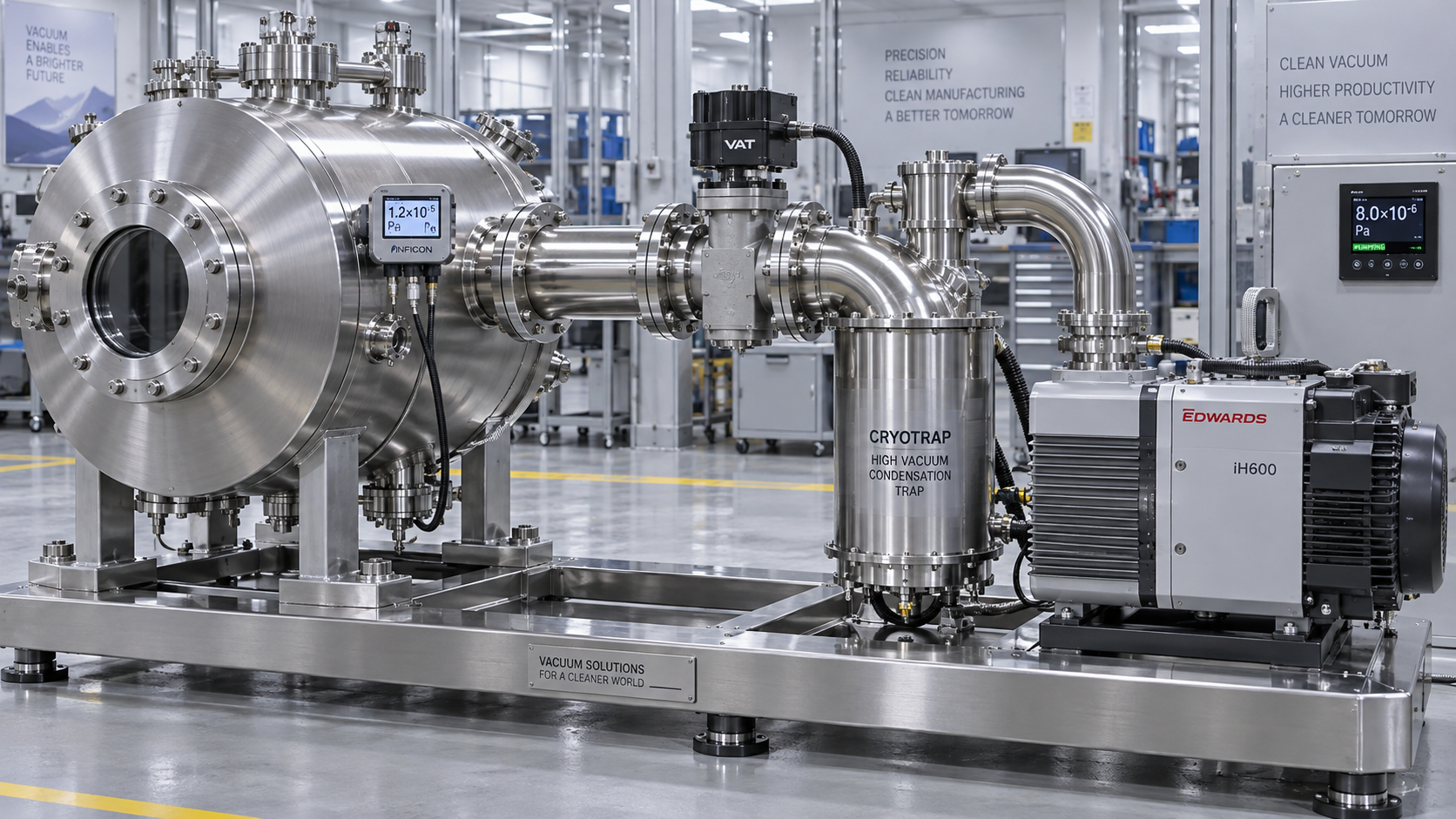
Ask suppliers to identify where deposits are most likely to form—not only inside the pump, but also in the foreline, exhaust connection, and abatement inlet. Heating, insulation, controlled purge flows, traps, and cleanable sections may be appropriate, depending on the process. Each measure has trade-offs: a trap adds another maintenance item, while heating adds utility demand and needs controls that prevent cold spots without exceeding component limits.
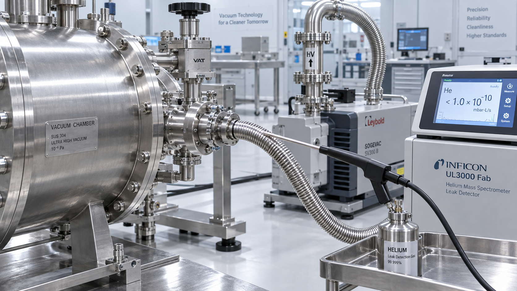
Contamination assessment should cover potential backstreaming, particle transport, leak integrity, and compatibility of wetted materials and seals. Include process changes in the discussion. A system qualified for one recipe family should not automatically be assumed suitable for a different material stack or cleaning chemistry.
Make purge strategy part of the specification
Nitrogen or another approved purge gas may protect pump mechanisms, dilute process species, or support safe transitions. Its effectiveness depends on flow, placement, timing, and the behavior of the complete system. Confirm the minimum and normal purge requirements, how loss of purge is detected, and what interlocks are necessary. Also include purge consumption in facility planning and operating-cost comparisons.
Check abatement and safety integration before approving the layout
The pump and abatement system must be compatible under both normal and abnormal conditions. Share the expected exhaust composition, flow, temperature, pressure, and variability with the abatement supplier. Confirm capacity for combined streams where applicable, and review whether maintenance or downtime on one tool affects others connected to shared equipment.
Safety review should address the actual gases and site rules, including toxic, corrosive, flammable, or otherwise hazardous materials where present. Examine isolation, ventilation, leak detection, emergency shutdown, purge sequencing, and safe access for maintenance. Do not rely on a pump’s materials list alone as evidence that the complete installation is safe.
Agree on responsibilities for interlocks and failure responses. A loss of cooling water, purge gas, power, or abatement availability may require a different response for each process. The tool maker, pump supplier, abatement supplier, and fab safety team should establish and validate those responses together.
Build a comparison around lifecycle performance
The lowest purchase price can be attractive during procurement, but it is only one part of the decision. Compare alternatives over a consistent planning period and make assumptions visible. Where site-specific figures are unavailable, use ranges or request supplier estimates rather than presenting uncertain values as guaranteed outcomes.
- Capital and installation: Pump, booster, controls, foreline modifications, abatement interfaces, commissioning, and necessary facility upgrades.
- Utilities: Electricity under representative operating states, cooling water, purge gas, heating, and any other required services.
- Maintenance: Inspection, cleaning, consumables, pump exchange, spare equipment, labor, and treatment of contaminated components.
- Production exposure: Planned downtime, recovery and requalification time, and the operational consequences of an unexpected failure.
- Supportability: Local service capability, spare-parts availability, diagnostic access, and clarity of supplier responsibilities.
Ask how proposed maintenance intervals were established and whether they reflect comparable chemistry, utilization, and byproduct loads. A generic interval is useful for planning, but actual condition and fab experience should determine the maintenance program after qualification.
Energy deserves the same contextual treatment. Compare power demand at process, standby, and other relevant states rather than relying only on motor nameplate ratings. Include auxiliary heating, cooling, and purge requirements where they differ between options. A lower pump power figure may not translate into lower system consumption if other utilities increase substantially.
Turn the shortlist into a qualification plan
Once the field is narrowed, document what each option must demonstrate. This makes the decision less dependent on persuasive specifications and gives all parties a shared definition of success.
- Set acceptance conditions. Identify the representative recipes, gas loads, pressure setpoints, transition tests, and utility conditions to be assessed.
- Define measurable outcomes. Include pressure stability, pumpdown behavior, alarms, utility consumption, and any contamination or process-monitoring checks required by the tool and fab.
- Review abnormal events. Test or otherwise validate agreed responses to utility loss, pump faults, purge faults, and abatement unavailability within approved safety procedures.
- Inspect maintainability. Verify access, isolation, decontamination provisions, exchange procedures, and the practical time needed to return equipment to service.
- Assign owners. Record who will collect data, resolve interface issues, approve deviations, and authorize production use.
Where a production trial is possible, monitor trends long enough to capture relevant recipe variation and early signs of deposition. If a trial is not feasible, scrutinize supplier evidence and state the remaining uncertainties explicitly. An assumption logged before purchase is easier to manage than an unexplained restriction after installation.
Choosing with confidence
The strongest vacuum process solutions for semiconductor etching are not necessarily the largest pumps or the options with the most impressive standalone specifications. They are the configurations whose pressure-control capability, chemistry compatibility, exhaust treatment, safety measures, and maintenance plan match the actual process envelope.
For engineering teams comparing competing proposals, a useful final question is: What would cause this system to drift out of specification, and how would we know? A supplier that can answer clearly—with defined interfaces, test conditions, and maintenance assumptions—gives evaluators a more reliable basis for a decision. GTC-Matrix follows these connections between vacuum performance, thermal management, and industrial efficiency to support that kind of informed assessment.
Ready when you are. Send us a message to get started.
Related News
- How to select vacuum process solutions for semiconductor etchingAuthor :Vacuum Process Fellow

- Can vacuum process optimization software reduce pump-down time?Author :Vacuum Process Fellow

- How does base pressure affect film purity in vacuum deposition?Author :Vacuum Process Fellow

- How to size vacuum process equipment for the required pump-down timeAuthor :Vacuum Process Fellow

- Which vacuum specification best protects semiconductor process yield?Author :Vacuum Process Fellow

- How Can Contamination Be Prevented in a Semiconductor Vacuum Chamber?Author :Vacuum Process Fellow

- Which Vacuum Pump Specifications Matter Most for Semiconductor Processes?Author :Vacuum Process Fellow

- How to find leaks in vacuum pump systems before pump performance dropsAuthor :Vacuum Process Fellow

- How to size a Roots blower for vacuum process equipmentAuthor :Vacuum Process Fellow

- How vacuum level affects vacuum process efficiencyAuthor :Vacuum Process Fellow

- China Imposes Temporary Helium Export BanAuthor :Vacuum Process Fellow

- Semiconductor Vacuum Systems Factory Checklist for Process Stability and Cleanroom UseAuthor :Vacuum Process Fellow

- Vacuum Process Optimization Services: Signs Your Line Needs a Performance ReviewAuthor :Vacuum Process Fellow

- Vacuum Chambers for Cleanroom Use: Key Design Points That Prevent ContaminationAuthor :Vacuum Process Fellow

- Vacuum Distillation Systems: Key Performance Metrics That Affect Product PurityAuthor :Vacuum Process Fellow

- Vietnam Halts High Vacuum Pump Import Licenses for 30 DaysAuthor :Vacuum Process Fellow

- Vacuum Technology Database: What to Check Before Using Technical DataAuthor :Vacuum Process Fellow

- Dry Pump Vacuum System Design Mistakes That Raise DowntimeAuthor :Vacuum Process Fellow

- When Vacuum Systems Lose Performance: Common Causes and FixesAuthor :Vacuum Process Fellow
![]()
- EU Tightens EN 13445-3 Weld Testing for Vacuum VesselsAuthor :Vacuum Process Fellow
![]()
- EPA Cuts R-1234ze(E) Quota 35%, Tightening Vacuum Cooling SupplyAuthor :Vacuum Process Fellow
 Quota 35%, Tightening Vacuum Cooling Supply")
- ICA Warns of Tight Copper Alloy Supply for Vacuum PumpsAuthor :Vacuum Process Fellow

- Vacuum System Leak Detection: Signs, Tests, and FixesAuthor :Vacuum Process Fellow

- How to Compare Vacuum Systems Factory Capabilities for Stable Process UptimeAuthor :Vacuum Process Fellow

- Vacuum Pump Lead Times Extend to 26 WeeksAuthor :Vacuum Process Fellow

- Semiconductor Vacuum Systems Explained for Stable Process YieldAuthor :Vacuum Process Fellow

- Vacuum Process Efficiency: 7 Hidden Causes of Energy LossAuthor :Vacuum Process Fellow

- Vacuum Technology Solutions for Stable Low-Pressure ProductionAuthor :Vacuum Process Fellow

- Vacuum Processes: Common Efficiency Losses and FixesAuthor :Vacuum Process Fellow

- Common Vacuum Processes Problems and How to Prevent DowntimeAuthor :Vacuum Process Fellow

- Tantalum Spike Extends Vacuum Crucible Lead TimesAuthor :Vacuum Process Fellow

- Vacuum Process Efficiency: 5 Hidden Losses to Check FirstAuthor :Vacuum Process Fellow

- How Heat Transfer Design Impacts Vacuum Process EfficiencyAuthor :Vacuum Process Fellow

- EN 13445-4:2026 Takes Effect for High-Vacuum ComponentsAuthor :Vacuum Process Fellow

- EU Vacuum Components Face New EN 13445-4:2026 Leak Test RuleAuthor :Vacuum Process Fellow

- UBS: Fed Cut View May Ease Vacuum Pump Lead TimesAuthor :Vacuum Process Fellow