



How to size a Roots blower for vacuum process equipment




A Roots blower is sized correctly when its effective pumping speed at the required operating pressure can remove the real gas load while its backing pump can accept the resulting discharge flow. Nominal displacement alone is not enough. A blower that looks large on a catalogue sheet may still fail to reach target pressure if the backing pump is undersized, the gas load rises during processing, or the blower is asked to operate across an excessive pressure differential.
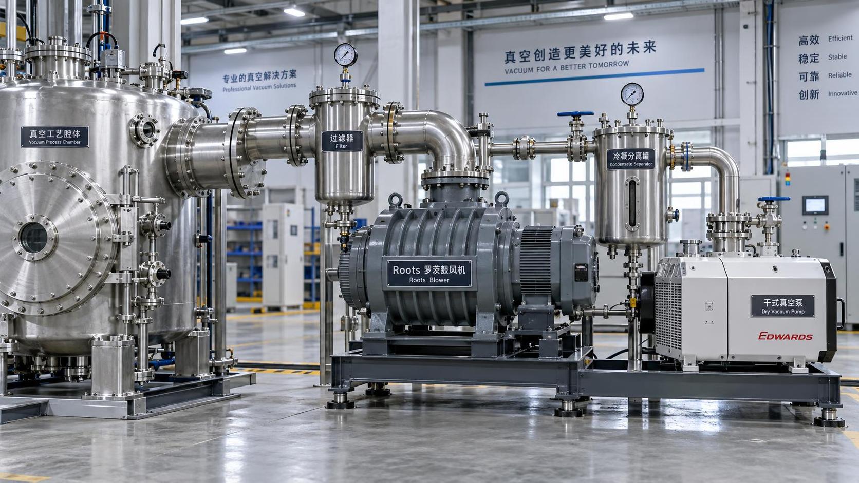
This issue often appears during technical evaluation of coating chambers, drying systems, degassing vessels, vacuum furnaces, and process skids. The system may evacuate an empty chamber quickly, yet pressure stalls once product, vapour, purge gas, or a heated load is introduced. In other cases, the blower runs hot, its bypass opens frequently, or the backing pump becomes the real bottleneck. Proper sizing starts by defining the process load at pressure, then checking the complete pump train rather than selecting a Roots blower in isolation.
Start with the pressure range that matters
Separate the vacuum cycle into stages before calculating capacity. Pump-down from atmospheric pressure, rough vacuum operation, process pressure control, and final evacuation do not impose the same duty on a Roots blower.
Roots blowers are most useful in the medium-vacuum range, where a mechanical backing pump alone no longer provides enough pumping speed. They are generally started only after the backing pump has reduced system pressure to a safe engagement level. The exact starting pressure depends on blower design, motor power, cooling arrangement, gas properties, and the permitted differential pressure across the machine.
For selection purposes, define at least four pressure points:
- Initial engagement pressure: the pressure at which the Roots blower starts or bypass operation becomes acceptable.
- Normal operating pressure: the pressure required during the actual process, not merely the final no-load vacuum level.
- Maximum process pressure: the highest pressure expected when gas release, vapour generation, or intentional gas injection is at its peak.
- Required end pressure: the lowest pressure needed after gas load declines, including any hold period or downstream transfer requirement.
A blower selected only for the end pressure can be misleading. Most industrial vacuum processes are limited by throughput during the operating phase, not by the ultimate pressure measured on an empty, clean system.
Calculate gas load before choosing pumping speed
The fundamental relationship is:
Q = p × S
where Q is gas throughput, p is absolute inlet pressure, and S is effective pumping speed at that pressure. Rearranged for preliminary sizing:
S required = Q total / p operating
Use consistent units throughout the calculation. Throughput may be expressed in Pa·m³/s, mbar·m³/h, Torr·L/s, or another internally consistent combination. The calculation is simple; assembling a realistic value for total gas load is the harder part.
Total throughput should include more than the intentional process gas flow. Depending on the equipment, it may contain:
- continuous purge, carrier, blanketing, or dilution gas;
- gas released from the product, fixtures, porous materials, or solvent residues;
- water vapour or condensable vapours generated by heating;
- leakage through seals, valves, flanges, shaft penetrations, and access doors;
- outgassing from chamber walls, insulation, elastomers, and internal surfaces;
- gas admitted during pressure-control actions, backfill steps, or valve transitions.
For an existing process, measured gas flow and pressure trends are often more valuable than assumptions. A pressure trace showing a stable plateau while gas is introduced can help estimate the actual pumping duty. For a new system, use the highest credible sustained load rather than a short, idealized average. A short vapour surge may be handled by vessel volume or control logic; a sustained load must be handled by the pump train.
Do not confuse blower displacement with usable system speed
Roots blower catalogues commonly state a nominal pumping speed based on geometric displacement. The effective speed available at the chamber is lower after considering conductance losses, internal slip, inlet restrictions, pressure-dependent behaviour, and the backing-pump operating point.
A practical evaluation should distinguish among three values:
Long or narrow inlet piping can erase much of the benefit of a larger blower. In the viscous-flow region, line losses are strongly influenced by pipe diameter, length, fittings, and gas flow. As pressure decreases and molecular-flow effects become more important, conductance may become even more restrictive. The combined relationship is commonly expressed as:
1 / S chamber = 1 / S pump + 1 / C line
Here, C line is the conductance of the connection between chamber and pump. When line conductance is low, increasing blower size produces limited improvement. A shorter, wider suction line with fewer elbows may be more effective than moving to the next blower frame size.
The backing pump sets the real operating boundary
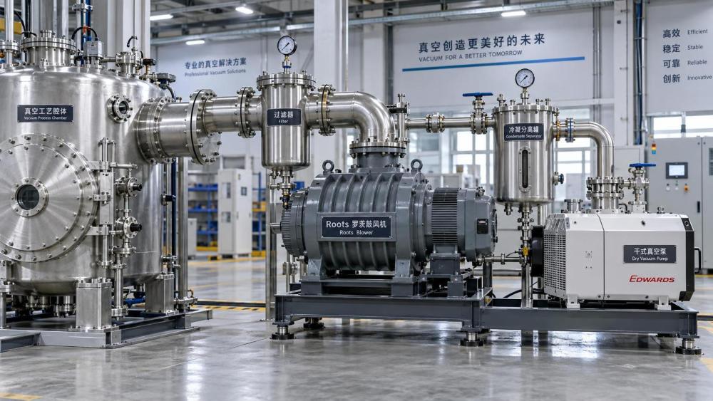
A Roots blower compresses gas from its inlet pressure to the backing-pump inlet pressure. It does not discharge directly to atmosphere in normal vacuum service. Its permissible compression ratio and differential pressure are therefore tied to the backing pump’s capacity.
At steady state, the backing pump must process approximately the same mass flow handled by the blower, but at a higher inlet pressure. If the backing pump cannot maintain sufficiently low foreline pressure, the Roots blower sees a rising differential pressure. This can increase power demand, generate heat, activate a bypass valve, trip protection systems, or force the blower to operate below its expected performance.
When sizing the backing pump, evaluate its pumping speed and gas-handling ability at the actual foreline pressure, not only its free-air displacement. Consider whether it must tolerate water vapour, solvent vapours, particulates, corrosive species, or oxygen-rich mixtures. A backing pump selected solely by nominal capacity may be unsuitable where condensables dilute lubricant, deposits block passages, or process gas changes seal and material requirements.
Check the compression ratio at worst duty
The relevant pressure ratio is approximately the blower discharge pressure divided by blower inlet pressure, using absolute pressures. The discharge side is influenced by foreline losses and backing-pump performance. The inlet side is the process operating pressure. Low inlet pressure combined with a high foreline pressure produces a demanding ratio even when the mass flow seems modest.
Request or calculate performance at the expected inlet pressure, gas composition, and discharge condition. Avoid relying on a single “maximum allowable differential pressure” figure without understanding whether it applies to continuous operation, cold start, bypass operation, or a limited part of the speed range.
Account for process gas, not just dry air
A vacuum process equipment Roots blower may handle dry air only during leak testing, then see a very different duty during production. Gas composition changes power, temperature, corrosion exposure, sealing requirements, and backing-pump behaviour.
Water vapour and solvents are frequent sources of sizing errors. A process may release a moderate mass of vapour but impose a high volumetric load at low absolute pressure. If the vapour condenses in the inlet line, blower, separator, or backing pump, apparent pumping performance can become unstable. Heated lines, knock-out vessels, condensers, cold traps, gas ballast, or dry backing technology may be needed depending on the vapour and process conditions.
Particulate-bearing streams require equal caution. Roots blowers have close internal clearances. Dust, polymer fragments, metal fines, or sticky deposits can reduce efficiency and cause mechanical damage. Inlet filtration should protect the equipment without introducing excessive pressure loss. The filter’s clean and dirty differential pressure must both be included when estimating available chamber speed.
For corrosive, reactive, toxic, or flammable gases, material compatibility and containment are selection criteria rather than optional accessories. Seal arrangement, purge provisions, monitoring points, exhaust treatment, and maintenance access may affect which blower and backing-pump configuration is acceptable. The pumping-speed calculation remains necessary, but it cannot override safe gas-handling requirements.
Use pump-down time as a separate check
A process may require both a sustained operating throughput and a defined evacuation time. These are related but different duties. Pump-down time depends on chamber volume, starting pressure, target pressure, changing pumping speed across the pressure range, internal gas release, and valve sequencing.
A simplified constant-speed estimate is often written as:
t = (V / S) × ln(p initial / p final)
This equation is useful only as an early screen. In a real system, pumping speed is not constant from atmospheric pressure to operating vacuum, the Roots blower may not start immediately, and outgassing can dominate the final part of pump-down. Treat the result as a preliminary comparison between alternatives, then confirm it with pressure-dependent pump curves and the planned control sequence.
Do not oversize the Roots blower merely to meet a pump-down target that is actually limited by a small isolation valve, a restrictive hose, trapped volumes, or a late blower start setpoint. Conversely, a large chamber with a tight cycle time may justify a larger blower even when steady-state gas load is low.
A practical selection sequence
- Define the chamber volume, required pressure profile, cycle time, and expected operating hours.
- Build a gas-load estimate for each process stage, separating continuous loads from short-duration peaks.
- Calculate required effective speed at the operating pressure using total throughput divided by absolute pressure.
- Estimate inlet conductance and determine the pumping speed that must be available at the blower inlet to achieve the required chamber speed.
- Select candidate Roots blowers using performance curves at the actual pressure range, not only nominal displacement.
- Match the backing pump by checking foreline pressure, gas throughput, vapour tolerance, and continuous-duty limits.
- Verify differential pressure, motor power, cooling demand, bypass behaviour, and startup interlocks at the highest credible load.
- Review line sizing, filtration, condensate management, instrumentation placement, and maintenance exposure before finalizing the package.
Signs that the preliminary blower size is wrong
Several operating symptoms point to a mismatch between calculated duty and installed capacity. A pressure plateau above the target during production usually indicates insufficient effective pumping speed, a larger-than-expected gas load, or restricted conductance. Frequent bypass opening can indicate excessive differential pressure or inadequate backing performance. A rising foreline pressure often directs attention to the backing pump, exhaust restriction, condensate accumulation, or an undersized foreline.
High blower temperature deserves prompt investigation. It may result from high compression ratio, sustained bypass operation, gas recirculation, insufficient cooling, or a process gas condition outside the intended duty. Simply increasing blower size does not always correct this problem; the foreline and backing-pump arrangement may need to change first.
The final selection should be based on the worst credible operating point, while avoiding a configuration so oversized that it creates unnecessary capital cost, power consumption, valve-control difficulty, or excessive inrush on startup. The strongest technical justification is a documented match between process throughput, chamber-side effective speed, inlet conductance, blower differential limit, and backing-pump capacity across the full vacuum cycle.
Related News
- How to size a Roots blower for vacuum process equipmentAuthor :Vacuum Process Fellow

- How vacuum level affects vacuum process efficiencyAuthor :Vacuum Process Fellow

- China Imposes Temporary Helium Export BanAuthor :Vacuum Process Fellow

- Semiconductor Vacuum Systems Factory Checklist for Process Stability and Cleanroom UseAuthor :Vacuum Process Fellow

- Vacuum Process Optimization Services: Signs Your Line Needs a Performance ReviewAuthor :Vacuum Process Fellow

- Vacuum Chambers for Cleanroom Use: Key Design Points That Prevent ContaminationAuthor :Vacuum Process Fellow

- Vacuum Distillation Systems: Key Performance Metrics That Affect Product PurityAuthor :Vacuum Process Fellow

- Vietnam Halts High Vacuum Pump Import Licenses for 30 DaysAuthor :Vacuum Process Fellow

- Vacuum Technology Database: What to Check Before Using Technical DataAuthor :Vacuum Process Fellow

- Dry Pump Vacuum System Design Mistakes That Raise DowntimeAuthor :Vacuum Process Fellow

- When Vacuum Systems Lose Performance: Common Causes and FixesAuthor :Vacuum Process Fellow
![]()
- EU Tightens EN 13445-3 Weld Testing for Vacuum VesselsAuthor :Vacuum Process Fellow
![]()
- EPA Cuts R-1234ze(E) Quota 35%, Tightening Vacuum Cooling SupplyAuthor :Vacuum Process Fellow
 Quota 35%, Tightening Vacuum Cooling Supply")
- ICA Warns of Tight Copper Alloy Supply for Vacuum PumpsAuthor :Vacuum Process Fellow

- Vacuum System Leak Detection: Signs, Tests, and FixesAuthor :Vacuum Process Fellow

- How to Compare Vacuum Systems Factory Capabilities for Stable Process UptimeAuthor :Vacuum Process Fellow

- Vacuum Pump Lead Times Extend to 26 WeeksAuthor :Vacuum Process Fellow

- Semiconductor Vacuum Systems Explained for Stable Process YieldAuthor :Vacuum Process Fellow

- Vacuum Process Efficiency: 7 Hidden Causes of Energy LossAuthor :Vacuum Process Fellow

- Vacuum Technology Solutions for Stable Low-Pressure ProductionAuthor :Vacuum Process Fellow

- Vacuum Processes: Common Efficiency Losses and FixesAuthor :Vacuum Process Fellow

- Common Vacuum Processes Problems and How to Prevent DowntimeAuthor :Vacuum Process Fellow

- Tantalum Spike Extends Vacuum Crucible Lead TimesAuthor :Vacuum Process Fellow

- Vacuum Process Efficiency: 5 Hidden Losses to Check FirstAuthor :Vacuum Process Fellow

- How Heat Transfer Design Impacts Vacuum Process EfficiencyAuthor :Vacuum Process Fellow

- EN 13445-4:2026 Takes Effect for High-Vacuum ComponentsAuthor :Vacuum Process Fellow

- EU Vacuum Components Face New EN 13445-4:2026 Leak Test RuleAuthor :Vacuum Process Fellow

- UBS: Fed Cut View May Ease Vacuum Pump Lead TimesAuthor :Vacuum Process Fellow

- Vacuum Processes: Common Causes of Unstable PerformanceAuthor :Vacuum Process Fellow
![]()
- SiC Certification Signals New Entry Path for Vacuum and Compressor DrivesAuthor :Vacuum Process Fellow
![]()
- How to Choose the Right Vacuum System for Process StabilityAuthor :Vacuum Process Fellow

- Vacuum Technology Selection: What Matters Most for Stable Process PerformanceAuthor :Vacuum Process Fellow

- Vacuum Processes: How to Reduce Contamination and Improve Cycle ConsistencyAuthor :Vacuum Process Fellow

- ITC 337 Probe Puts TOPCon Supply Chain Under ReviewAuthor :Vacuum Process Fellow

- Vacuum Process Efficiency: Where Energy Loss Really StartsAuthor :Vacuum Process Fellow

- Vacuum Technology: When High Vacuum Is Worth the UpgradeAuthor :Vacuum Process Fellow
![]()