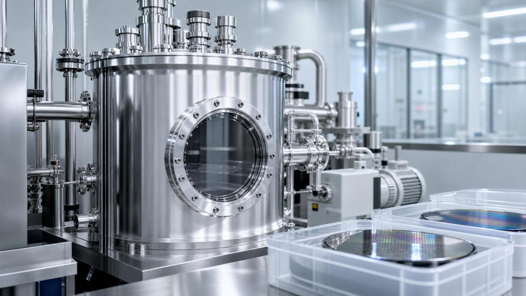




How Can Contamination Be Prevented in a Semiconductor Vacuum Chamber?




Semiconductor vacuum chamber contamination can quietly undermine an otherwise well-controlled process. A few particles released from a worn component, a trace of moisture introduced during venting, or a small backstreaming event from a pump can change film properties, distort critical dimensions, and create yield loss that only becomes visible after wafers have moved downstream.
So, how do I prevent contamination in a semiconductor vacuum chamber? The practical answer is not a single cleaning step or a better filter. Contamination prevention is a disciplined system that connects chamber design, material compatibility, gas delivery, vacuum performance, wafer handling, cleaning chemistry, and maintenance behavior. When these controls work together, the chamber becomes more stable, recovery after preventive maintenance is faster, and process results are easier to trust.
For process engineers, facilities teams, equipment owners, and suppliers supporting high-purity manufacturing, the goal is simple: keep unwanted matter from entering the chamber, minimize what is generated inside it, and remove residues before they become a process variable.
Start by Defining What “Contamination” Means for Your Process
Not all contamination behaves the same way. A particle problem in a plasma etch chamber may have a different origin from metal contamination in a deposition tool or hydrocarbon residue in a high-vacuum analytical process. Before selecting controls, identify the contaminant classes that matter most to the specific process.
- Particles: flakes from deposited films, chamber wall residues, mechanical wear, degraded seals, fibers, or particles carried in through gas and wafer handling systems.
- Metallic contamination: material transferred from fixtures, shields, fasteners, sputter targets, tooling, or incorrectly selected cleaning tools.
- Organic contamination: pump oil vapor, lubricants, fingerprints, packaging residues, polymers, solvents, and outgassing from unsuitable materials.
- Moisture and oxygen: commonly introduced through leaks, incomplete purging, wet components, long chamber openings, or poorly controlled venting procedures.
- Cross-process residues: chemistry or film remnants carried from a previous recipe, product family, or maintenance activity.
This classification matters because a chamber can pass a general vacuum test yet still be unsuitable for a sensitive process. A base pressure reading tells part of the story; residual gas composition, particle behavior, wall condition, and the repeatability of the pumpdown curve often reveal much more.
Build Contamination Control Around the Chamber’s Entire Life Cycle
Many contamination events are created long before a wafer enters the tool. They begin with a material choice, an uncontrolled maintenance action, or an installation detail that seemed harmless at the time. The most reliable approach treats cleanliness as a condition maintained across installation, operation, service, and recovery.
Choose vacuum-compatible materials and components
Every material placed inside or near the vacuum envelope should be evaluated for outgassing, chemical compatibility, thermal stability, and particle shedding. Stainless steel, properly prepared aluminum alloys, ceramics, and process-qualified elastomers are common choices, but suitability still depends on temperature, plasma exposure, process gases, and pressure range.
Avoid introducing unqualified polymers, tapes, adhesives, lubricants, marker inks, cardboard fibers, or general-purpose gloves into the chamber environment. Even materials that appear clean can release volatile compounds under vacuum or become brittle and shed after repeated thermal cycling. For critical assemblies, use controlled cleaning, approved packaging, and documented handling procedures from receipt through installation.
Protect seals without turning them into a contamination source
Elastomer seals deserve particular attention. O-rings can absorb chemicals, trap particles, crack with age, or release residues if they are over-lubricated or cleaned with incompatible solvents. Inspect sealing surfaces under suitable lighting, replace visibly damaged seals, and use only the minimum amount of approved vacuum grease when the application requires it. In many high-cleanliness systems, dry assembly or metal sealing is preferred where design conditions allow.
During installation, do not drag an O-ring across a flange or touch it with bare hands. A small fiber or fingerprint at a sealing interface may later become both a leak path and an organic contamination source.

Keep the Vacuum System Clean, Not Just the Chamber
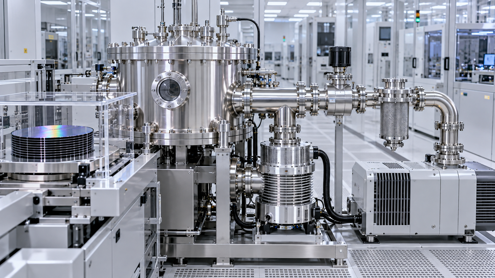
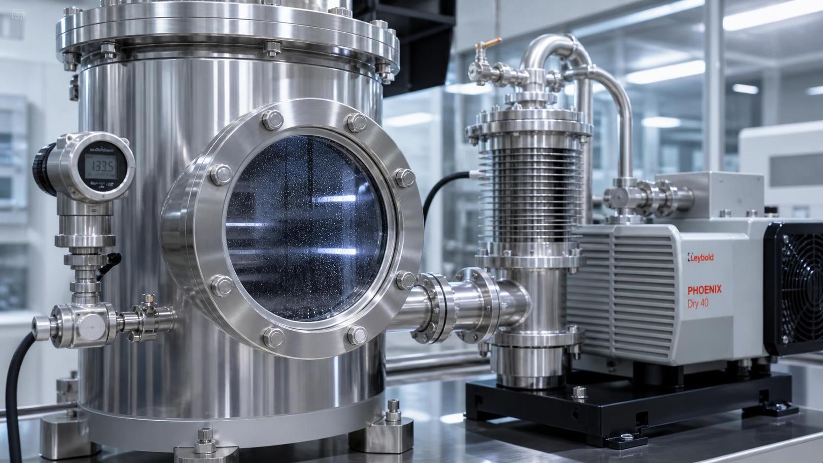
A chamber is only as clean as the vacuum path connected to it. Forelines, valves, traps, pumps, gauges, and exhaust components can all introduce contaminants if they are poorly matched to the process or inadequately maintained.
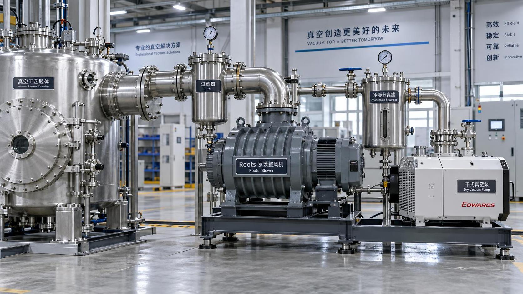
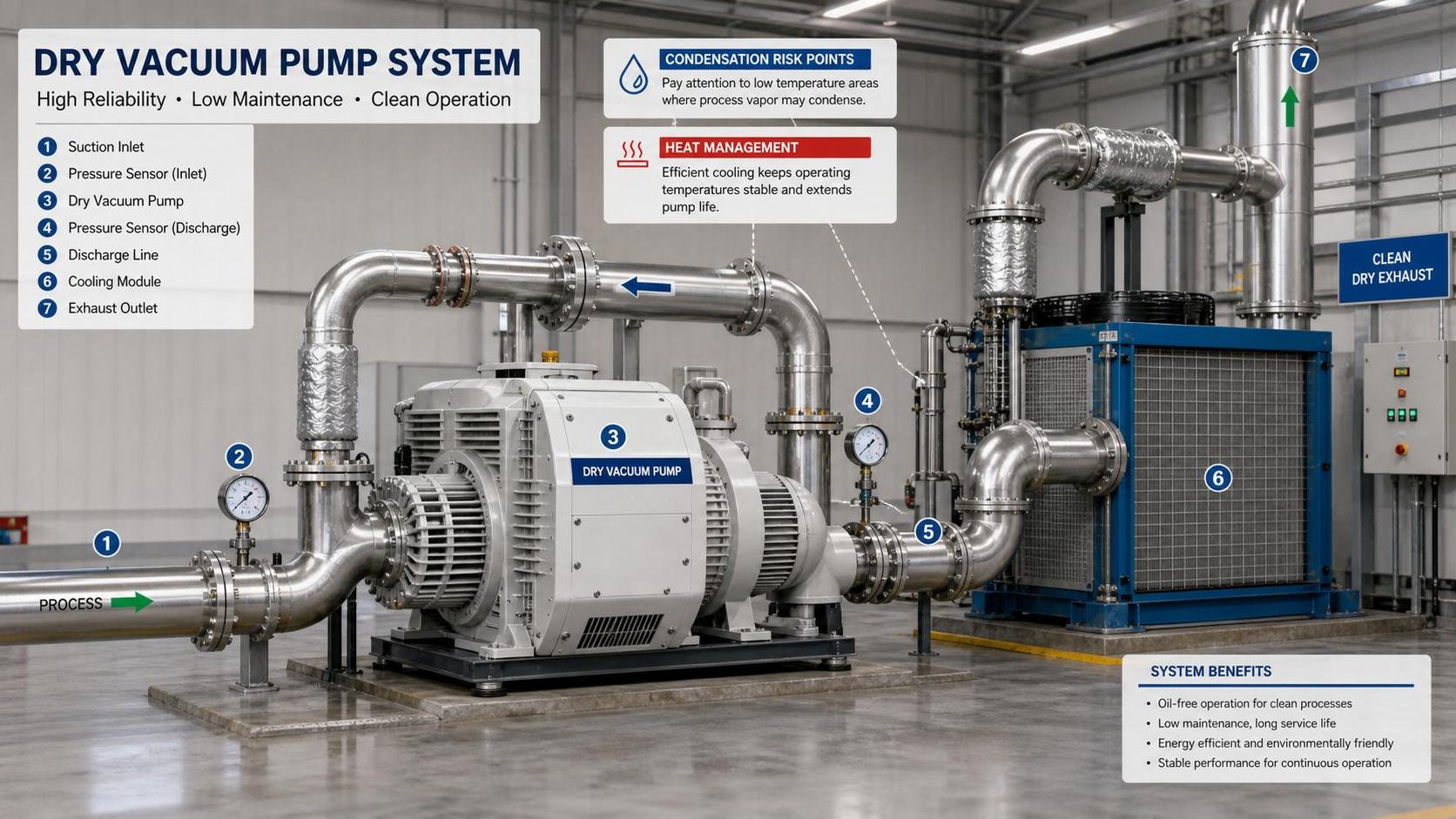
Oil-sealed mechanical pumps remain useful in many industrial vacuum systems, but they require careful isolation from semiconductor process chambers. Backstreaming of oil vapor can create hydrocarbon films that are difficult to remove and may affect adhesion, etch behavior, or thin-film uniformity. Use appropriate foreline traps, isolation valves, purge arrangements, and maintenance practices. Where process sensitivity justifies it, dry pumps and oil-free compression technologies reduce one important contamination pathway, though they still require disciplined service and particle control.
Do not overlook the condition of foreline piping. Condensed by-products, corrosion debris, and deposits can accumulate in low points or dead legs. A sudden pressure excursion, valve event, or temperature change may release this material back toward the process chamber. Keep lines properly routed, minimize unnecessary volumes, and schedule inspection or replacement based on process loading rather than waiting for an obvious failure.
Use vacuum performance as an early-warning signal
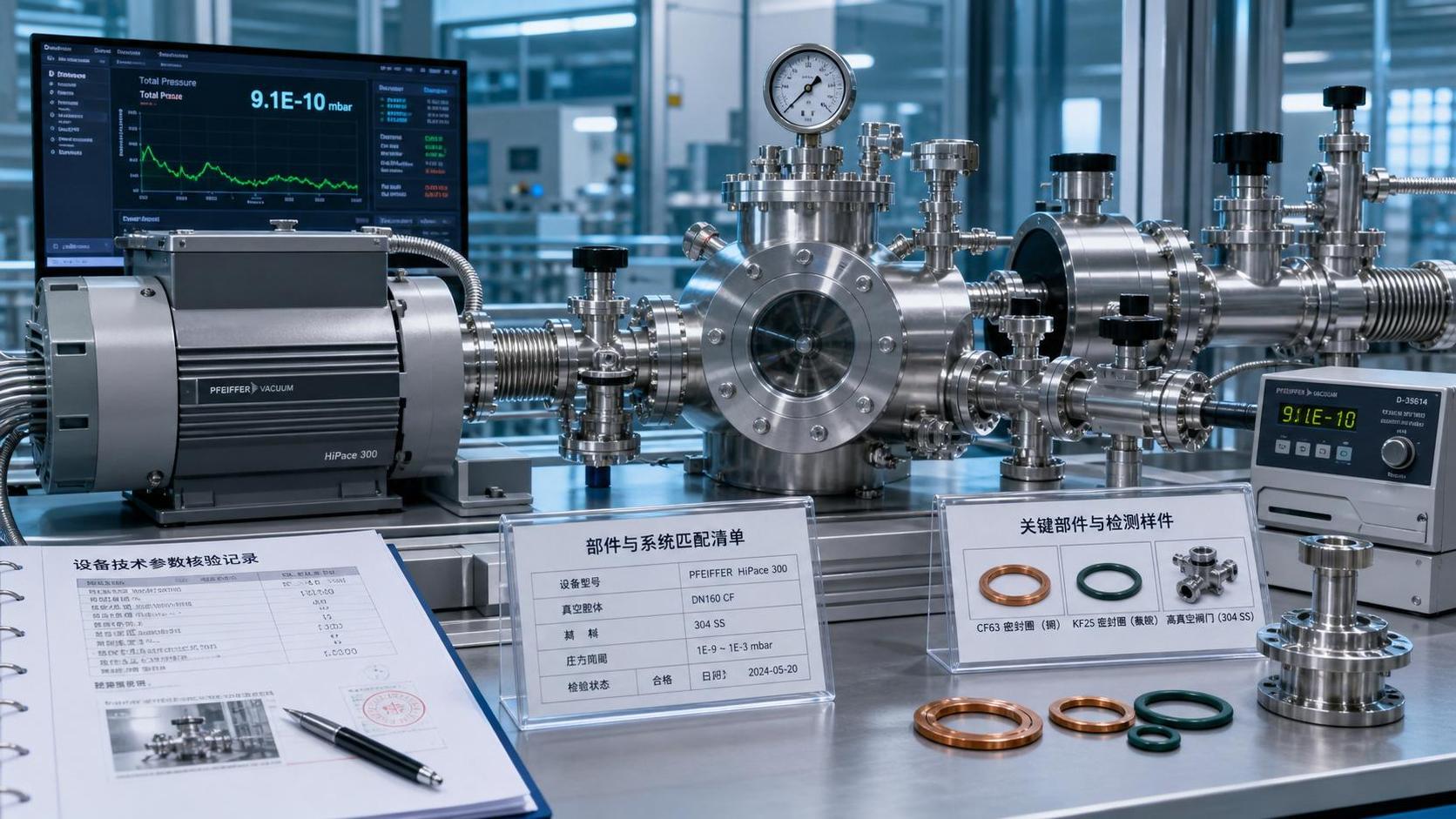
Stable pumpdown behavior is often more informative than a single ultimate-pressure measurement. Record baseline data after installation and after major chamber cleans: pumpdown time, base pressure, pressure rise after isolation, residual gas trends where available, and the time required to return to qualified process conditions.
If the chamber suddenly pumps down more slowly, reaches a different pressure plateau, or shows greater run-to-run variation, investigate before accepting it as normal drift. Possible causes include leaks, water adsorption, valve degradation, accumulated process residue, failing pump components, or contamination in the gas delivery system.
Control Gas Purity All the Way to the Point of Use
High-purity process gas purchased at the cylinder is not automatically high purity at the chamber. Contaminants can enter through regulators, fittings, dead legs, aged filters, contaminated cylinders, and improper changeover practices. In sensitive semiconductor operations, the gas distribution system must be treated as part of the process tool.
Use process-appropriate gas purification, compatible tubing, clean regulators, and validated point-of-use filtration where required. Minimize dead volumes where moisture or reactive residues can linger. After any gas-line intervention, follow a defined purge sequence rather than relying on a quick pressure cycle. The correct purge gas, flow direction, number of cycles, and vent path should reflect the chemistry involved.
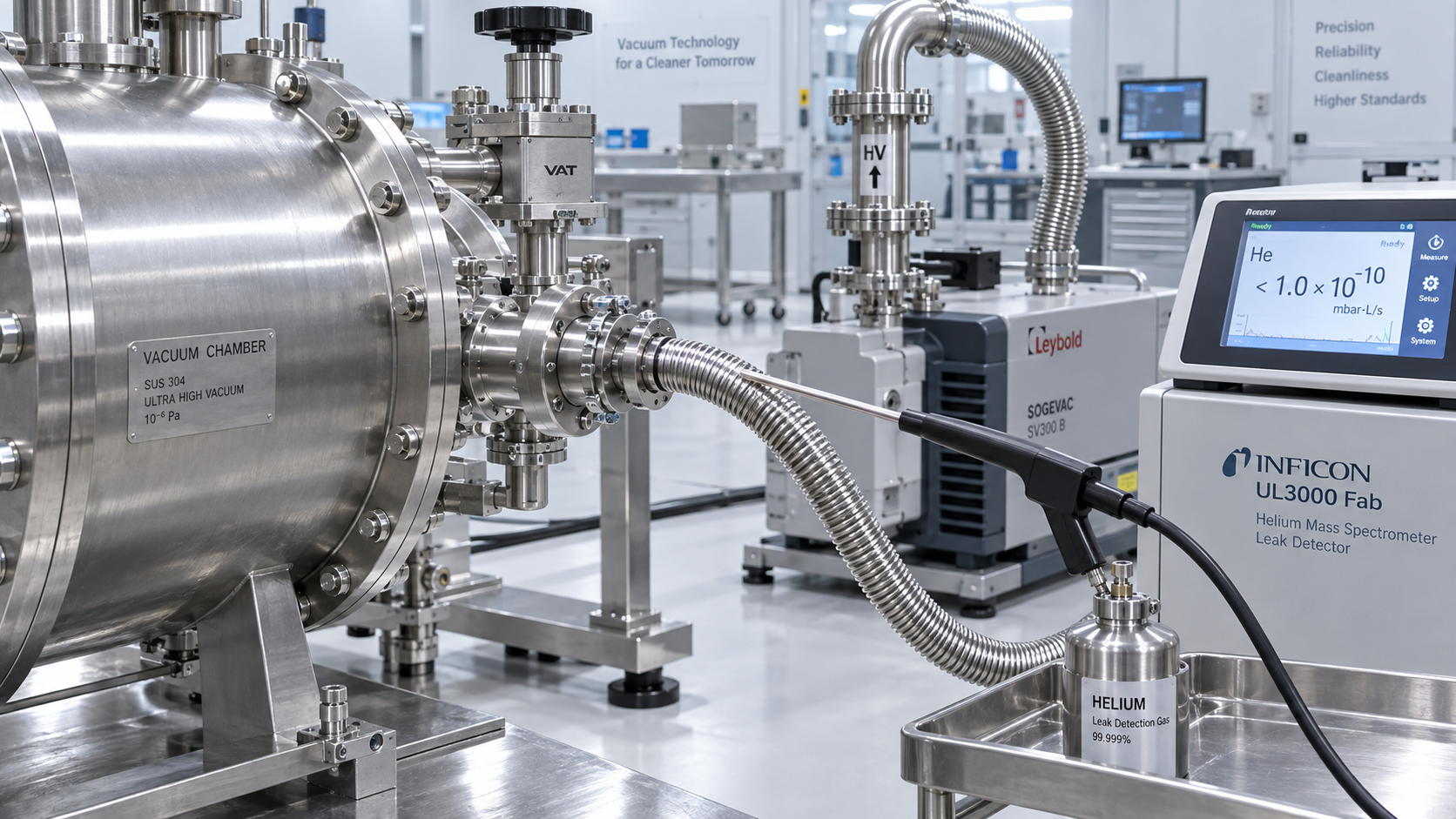
Leaks in gas systems are not only safety issues. An inward leak can introduce air, moisture, and hydrocarbons; an outward leak can destabilize gas delivery or create hazardous exposure. Helium leak checking, pressure decay testing, and connection inspections should be routine activities after maintenance, component replacement, or unexplained process variation.
Make Venting and Chamber Opening Deliberate Events
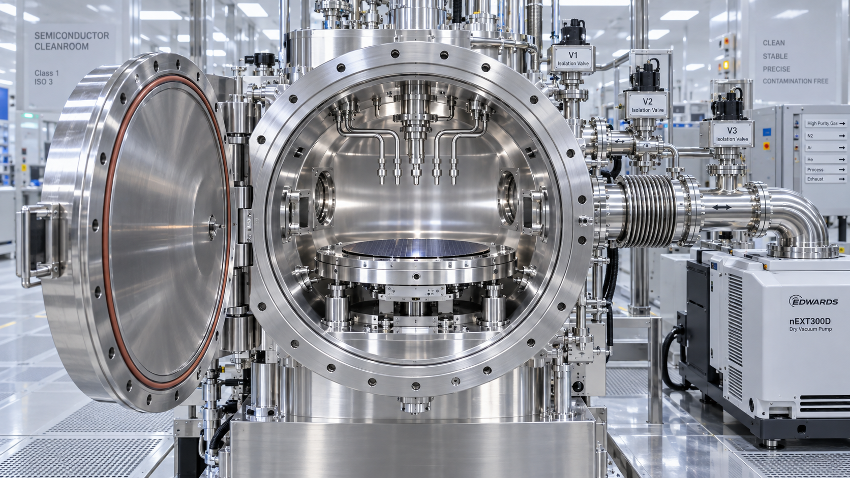
Opening a vacuum chamber is one of the highest-risk moments for contamination. The chamber walls are exposed, personnel are nearby, tools enter the work zone, and deposits that were stable under vacuum may flake or react with atmospheric moisture.
Vent with a clean, dry, compatible gas rather than uncontrolled room air whenever the process requirements justify it. A slow, controlled vent reduces turbulence and helps prevent loose particles from becoming airborne. Once atmospheric pressure is reached, limit the open duration and protect exposed surfaces from surrounding activity. Maintenance carts, packaging, tools, and replacement parts should arrive cleaned, bagged, and ready—not be wiped down beside the open chamber.
Human behavior matters here. Gloves must be clean and changed often enough to remain clean. Technicians should avoid leaning over chamber openings, placing paperwork nearby, or using unapproved wipes. These details can seem minor during a busy maintenance window, yet they are frequent sources of fibers, skin oils, and debris.
Clean for the Actual Residue, Not for Appearances
A chamber that looks clean is not necessarily process-clean. Deposits may be thin, transparent, chemically active, or located behind shields and in areas that are difficult to inspect. Effective cleaning begins with understanding the process chemistry and where residues are expected to accumulate.
For example, deposition processes may require regular shield replacement or cleaning to prevent film flaking. Plasma processes can leave polymerized residues on chamber walls, electrostatic chucks, focus rings, and gas distribution components. Wet cleaning, dry cleaning, plasma cleaning, bead blasting, ultrasonic cleaning, or parts replacement may each be appropriate in different circumstances—but the chosen method must not damage surfaces or introduce its own residue.
After cleaning, allow adequate recovery time. Pumpdown, bakeout, seasoning wafers, plasma conditioning, and test runs are not administrative delays; they stabilize the chamber before production material is exposed. Skipping recovery steps may create a false impression of faster turnaround while moving the risk directly onto product wafers.
Separate Preventive Maintenance From Emergency Repair Habits
When a tool is down, teams naturally want to restore production quickly. That pressure can lead to shortcuts: reusing a questionable seal, installing a part without complete cleaning verification, or postponing a leak check. In a semiconductor vacuum environment, these shortcuts often create a second, longer interruption later.
A robust preventive maintenance program identifies consumables and surfaces that degrade predictably. It establishes replacement intervals for filters, seals, shields, pump components, valve seats, and other parts based on process exposure, wafer count, operating hours, and observed chamber condition. The interval should be refined using actual trend data, not treated as a permanent fixed rule.
Maintain a clear service record for each chamber: what was opened, which parts were replaced, which cleaning method was used, leak-check results, recovery performance, and any process qualification outcome. This history is invaluable when recurring particles or drift appear. Without it, engineers are left comparing incomplete memories rather than evidence.
Monitor the Signals That Point to Contamination Before Yield Falls
Contamination is easier to manage when it is detected as a trend rather than as a yield excursion. Useful monitoring may include particle counts, wafer defect maps, residual gas analysis, pressure-rise testing, base-pressure trends, mass-flow stability, endpoint behavior, film measurements, and optical inspection of chamber components.
The right signals depend on the process, but the principle remains consistent: connect equipment health data with wafer results. A particle increase after a certain number of cycles, for instance, may indicate coating buildup on a shield. A recurring moisture signature after maintenance may point to inadequate drying, a leaking connection, or insufficient purge discipline.
For organizations managing energy-intensive thermal and vacuum infrastructure, this is also where process intelligence becomes valuable. Vacuum stability is not isolated from compressor performance, cooling conditions, purge gas quality, or utility reliability. GTC-Matrix follows these interdependencies across industrial vacuum, compressed air, cooling, and heat-exchange systems because cleaner process conditions often depend on a broader, well-managed utility ecosystem.
A Practical Contamination-Prevention Checklist
Before returning a semiconductor vacuum chamber to production, ask a few direct questions:
- Have all chamber-facing parts been cleaned, inspected, and handled in controlled packaging?
- Are seals, flanges, valves, and gas connections free from visible damage and verified for leaks?
- Is the pumping train protected from backstreaming, deposits, and worn components?
- Were approved gases, purges, wipes, lubricants, and cleaning chemicals used?
- Has the chamber completed its required pumpdown, conditioning, and qualification sequence?
- Do current vacuum and process trends match the established healthy baseline?
Preventing contamination in a semiconductor vacuum chamber is ultimately an exercise in consistency. Clean hardware alone is not enough. The most reliable fabs create repeatable habits around every chamber opening, every gas connection, every maintenance task, and every return-to-service decision. That discipline protects more than the chamber itself—it protects process stability, wafer yield, and confidence in the manufacturing line.
Related News
- How Can Contamination Be Prevented in a Semiconductor Vacuum Chamber?Author :Vacuum Process Fellow

- Which Vacuum Pump Specifications Matter Most for Semiconductor Processes?Author :Vacuum Process Fellow

- How to find leaks in vacuum pump systems before pump performance dropsAuthor :Vacuum Process Fellow

- How to size a Roots blower for vacuum process equipmentAuthor :Vacuum Process Fellow

- How vacuum level affects vacuum process efficiencyAuthor :Vacuum Process Fellow

- China Imposes Temporary Helium Export BanAuthor :Vacuum Process Fellow

- Semiconductor Vacuum Systems Factory Checklist for Process Stability and Cleanroom UseAuthor :Vacuum Process Fellow

- Vacuum Process Optimization Services: Signs Your Line Needs a Performance ReviewAuthor :Vacuum Process Fellow

- Vacuum Chambers for Cleanroom Use: Key Design Points That Prevent ContaminationAuthor :Vacuum Process Fellow

- Vacuum Distillation Systems: Key Performance Metrics That Affect Product PurityAuthor :Vacuum Process Fellow

- Vietnam Halts High Vacuum Pump Import Licenses for 30 DaysAuthor :Vacuum Process Fellow

- Vacuum Technology Database: What to Check Before Using Technical DataAuthor :Vacuum Process Fellow

- Dry Pump Vacuum System Design Mistakes That Raise DowntimeAuthor :Vacuum Process Fellow

- When Vacuum Systems Lose Performance: Common Causes and FixesAuthor :Vacuum Process Fellow
![]()
- EU Tightens EN 13445-3 Weld Testing for Vacuum VesselsAuthor :Vacuum Process Fellow
![]()
- EPA Cuts R-1234ze(E) Quota 35%, Tightening Vacuum Cooling SupplyAuthor :Vacuum Process Fellow
 Quota 35%, Tightening Vacuum Cooling Supply")
- ICA Warns of Tight Copper Alloy Supply for Vacuum PumpsAuthor :Vacuum Process Fellow

- Vacuum System Leak Detection: Signs, Tests, and FixesAuthor :Vacuum Process Fellow

- How to Compare Vacuum Systems Factory Capabilities for Stable Process UptimeAuthor :Vacuum Process Fellow

- Vacuum Pump Lead Times Extend to 26 WeeksAuthor :Vacuum Process Fellow

- Semiconductor Vacuum Systems Explained for Stable Process YieldAuthor :Vacuum Process Fellow

- Vacuum Process Efficiency: 7 Hidden Causes of Energy LossAuthor :Vacuum Process Fellow

- Vacuum Technology Solutions for Stable Low-Pressure ProductionAuthor :Vacuum Process Fellow

- Vacuum Processes: Common Efficiency Losses and FixesAuthor :Vacuum Process Fellow

- Common Vacuum Processes Problems and How to Prevent DowntimeAuthor :Vacuum Process Fellow

- Tantalum Spike Extends Vacuum Crucible Lead TimesAuthor :Vacuum Process Fellow

- Vacuum Process Efficiency: 5 Hidden Losses to Check FirstAuthor :Vacuum Process Fellow

- How Heat Transfer Design Impacts Vacuum Process EfficiencyAuthor :Vacuum Process Fellow

- EN 13445-4:2026 Takes Effect for High-Vacuum ComponentsAuthor :Vacuum Process Fellow

- EU Vacuum Components Face New EN 13445-4:2026 Leak Test RuleAuthor :Vacuum Process Fellow

- UBS: Fed Cut View May Ease Vacuum Pump Lead TimesAuthor :Vacuum Process Fellow

- Vacuum Processes: Common Causes of Unstable PerformanceAuthor :Vacuum Process Fellow
![]()
- SiC Certification Signals New Entry Path for Vacuum and Compressor DrivesAuthor :Vacuum Process Fellow
![]()
- How to Choose the Right Vacuum System for Process StabilityAuthor :Vacuum Process Fellow

- Vacuum Technology Selection: What Matters Most for Stable Process PerformanceAuthor :Vacuum Process Fellow

- Vacuum Processes: How to Reduce Contamination and Improve Cycle ConsistencyAuthor :Vacuum Process Fellow