



How to find leaks in vacuum pump systems before pump performance drops




A vacuum system can lose useful capacity long before the pump appears to be failing. A small air path through a gasket, valve stem, instrument fitting, flexible hose, chamber door, or weld defect raises the gas load continuously. The pump then runs longer to maintain the same pressure, evacuation time stretches, and process conditions become less repeatable. Finding the leak early starts with separating a true external leak from normal outgassing, trapped volume release, vapor loading, or an internal pump problem.
The most reliable approach is to establish a repeatable baseline, isolate sections of the system, and use a detection method that matches the required sensitivity and the system's materials. Randomly spraying joints or replacing seals without a pressure trend usually creates rework: a temporary improvement may be mistaken for a confirmed repair, while the original leak remains elsewhere.
Begin with a pressure behavior test
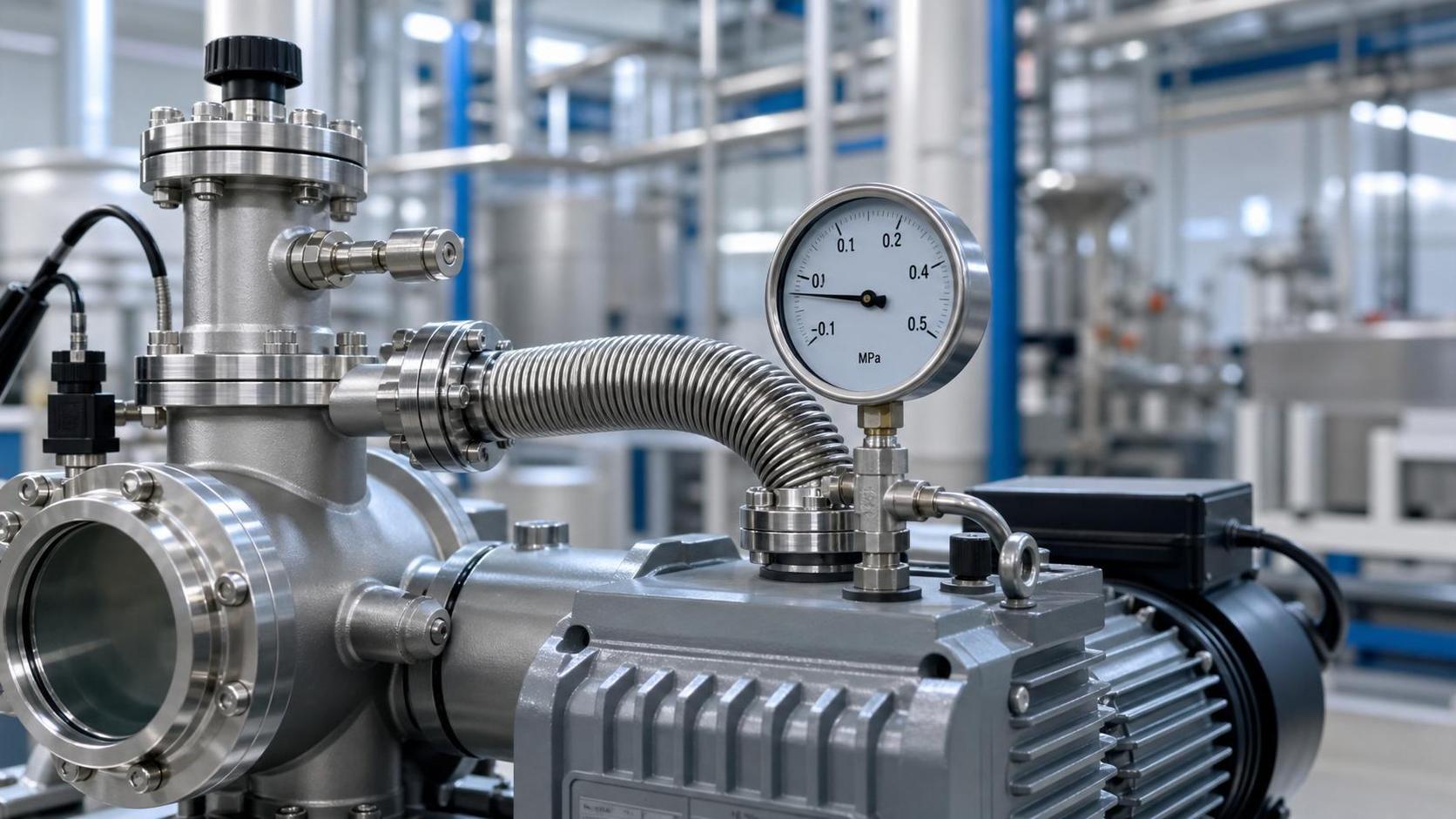
Before searching for a location, record how the system behaves from atmospheric pressure to its normal operating range. Use a gauge that is appropriate for that range. A roughing gauge can show whether the system reaches a low vacuum, but it cannot meaningfully diagnose a small leak near the pump's ultimate pressure. Conversely, a high-vacuum gauge may be unreliable at higher pressure or when its sensor is contaminated.
Start with the process chamber empty and as clean and dry as practical. Run the usual pump-down sequence, record the pressure at consistent time intervals, and note ambient conditions, pump temperature, valve positions, and any purge or gas ballast setting. Repeat the run after the system has stabilized thermally. A changing result between a cold and warm pump-down can reveal a seal that opens with temperature, a hose that softens under heat, or vapor that is being driven off internal surfaces rather than an air leak.
Then perform an isolation or rate-of-rise test. Evacuate the selected volume, close a valve that is known to seal, and watch the pressure increase over a fixed interval. A rapid, roughly linear rise often points toward a real incoming gas path. A curve that rises quickly at first and then slows is more consistent with desorption, moisture, or material outgassing. The shape alone is not proof, but it determines where to investigate next.
If pressure rises only while a certain branch is connected, do not begin at the pump. Isolate the chamber, foreline, filter housing, trap, receiver, manifold, and attached process equipment in sequence. The aim is to reduce a large system to the smallest leaking volume. This section-by-section method is faster than treating every joint as equally suspect.
Distinguish leakage from similar symptoms
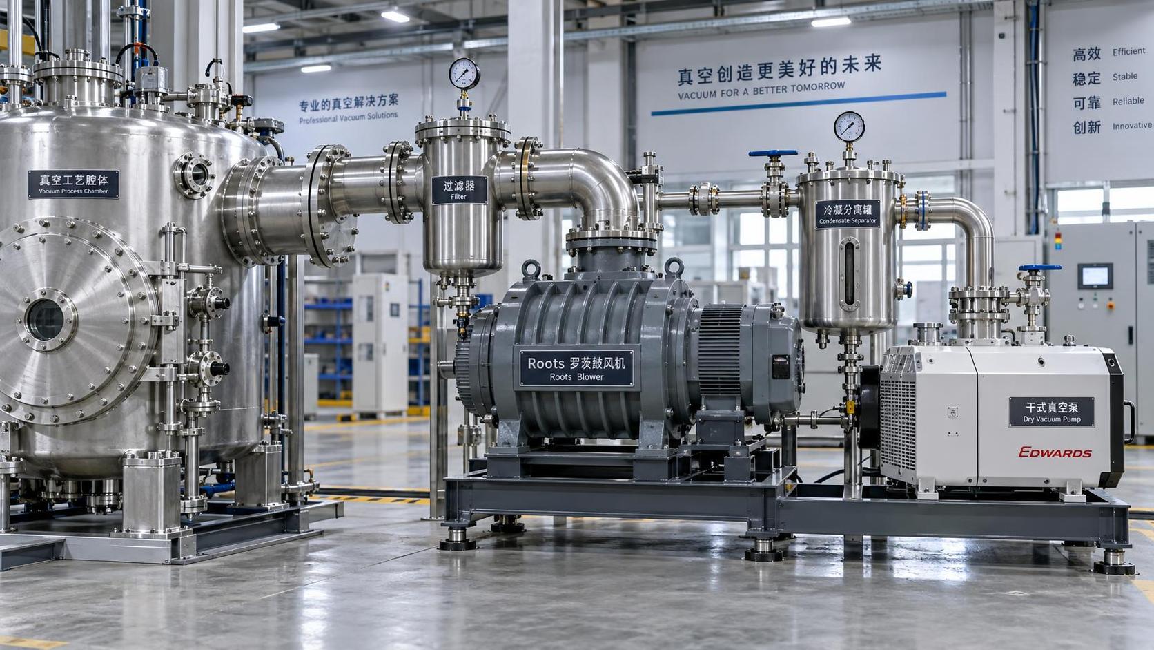
Poor ultimate pressure is not automatically a leak. An oil-sealed rotary vane pump with degraded oil, excessive water contamination, a blocked exhaust path, worn vanes, or an incorrectly set gas ballast can show the same broad symptom. A dry screw or claw pump may lose performance because of internal clearances, damaged timing components, overheating, or process deposits. Roots blowers and boosters introduce further possibilities: bypass valve issues, incorrect backing pressure, and leakage around shaft seals.
Run a blank-off test only in accordance with the pump manufacturer's procedure. The test removes the connected system and evaluates the pump independently. If the pump reaches its expected blanked-off condition but the installed system does not, the fault is downstream of the pump inlet. If the pump itself performs poorly, searching every chamber flange first wastes time. Never blank off a pump in a way that defeats required cooling, lubrication, exhaust handling, or pressure relief arrangements.
Outgassing also deserves careful treatment. Elastomers, adhesives, porous castings, wet product, cleaning residues, and warm polymer components release gas after evacuation. A chamber opened to humid air may show a stubborn pressure rise from adsorbed water even with no physical leak. Heating, purging, extending evacuation time, or drying the affected component may change that behavior. Replacing an O-ring will not solve a moisture-loaded process fixture.
Find the leak without contaminating the system
For rough-vacuum systems, a controlled local spray test is often useful. With the system under vacuum, apply a small amount of a suitable test fluid around one external joint at a time while observing the pressure signal. A temporary response indicates that the fluid has entered through a leak path. Keep the spray targeted and minimal. Excess fluid can be drawn into the process volume, attack incompatible elastomers, leave residues, or obscure the test by affecting several adjacent joints at once.
This method works best when the gauge responds quickly and the suspected area is accessible. It is less convincing around porous insulation, closely packed fittings, or long threaded connections, where fluid can migrate from its point of application. A response at a flange may originate from a nearby gauge connection, valve body, or cable feedthrough. Retest the individual components after shielding neighboring areas.
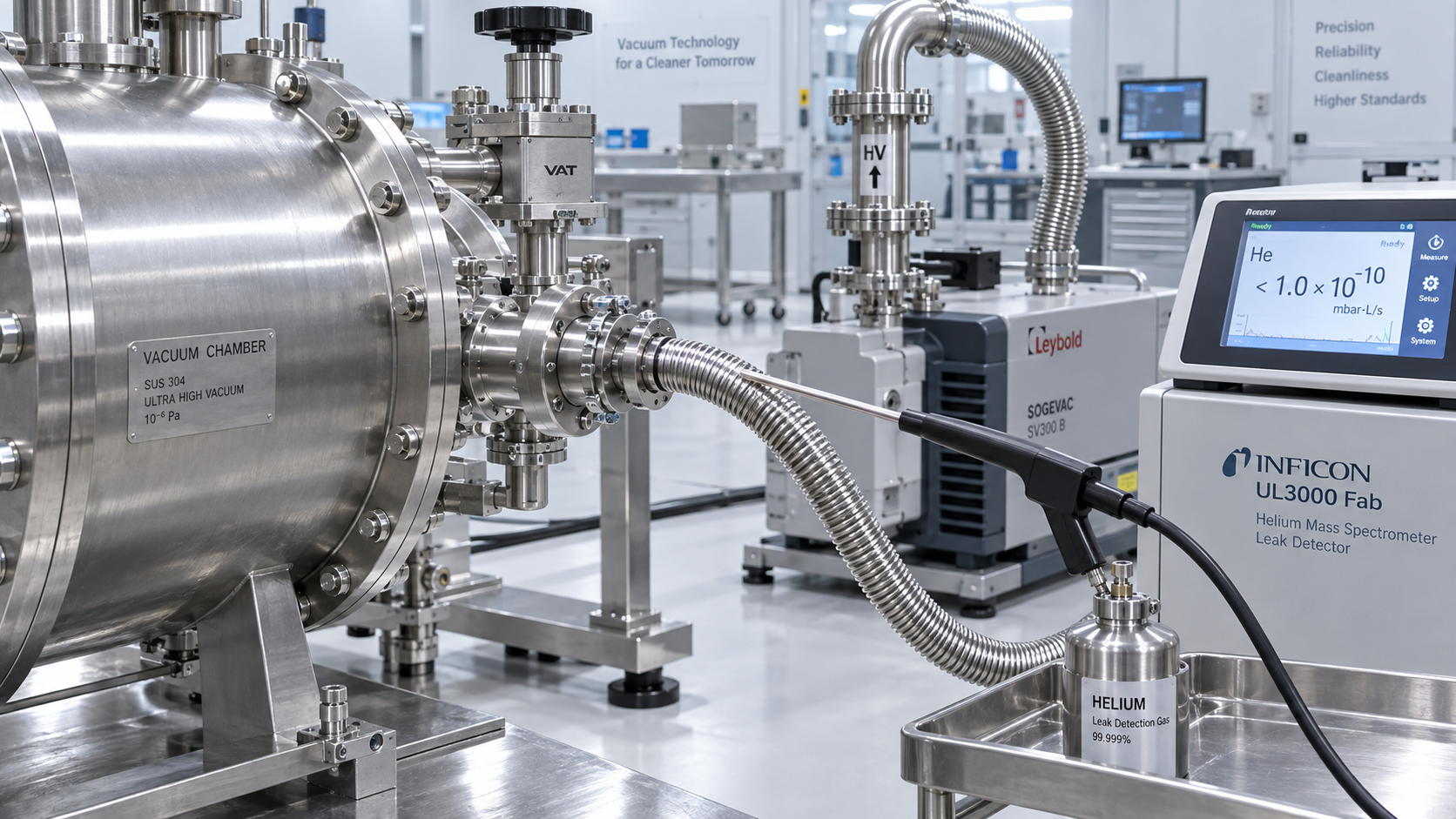
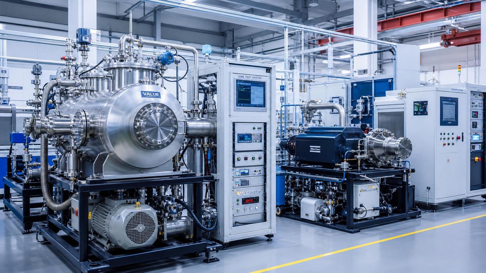
Helium mass spectrometer testing provides greater sensitivity and location precision, particularly for high-vacuum equipment, clean processes, semiconductor tools, coating chambers, analytical equipment, and assemblies with many welded joints. The system is evacuated and connected to a leak detector, then helium is applied externally in a disciplined pattern. The detector response identifies helium entering the vacuum boundary.
Good helium testing is controlled work, not broad spraying. Begin with a background reading and allow the detector to stabilize. Bag or hood a small region where possible, then move from larger boundaries to individual flanges, valves, and fittings. Helium lingers in the surrounding air and moves through gaps in panels, cable trays, and insulation. Once background rises, a signal can be falsely assigned to the most recently tested component. Ventilate the area, wait for the background to recover, and retest suspicious points from a different direction.
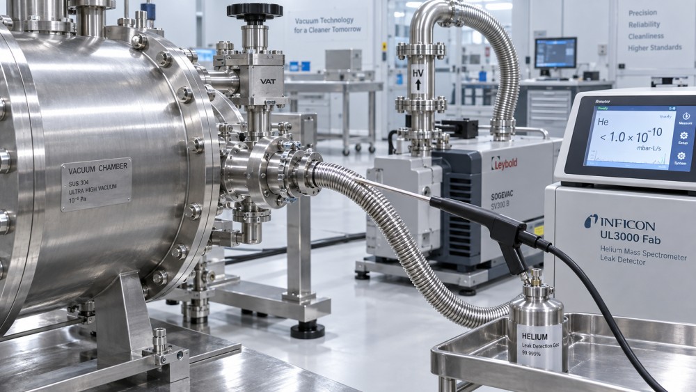
For systems that cannot be evacuated for a conventional outside-in test, pressure testing with a tracer gas and external sniffing may be appropriate, provided the pressure, gas selection, and safety controls match the equipment design. This approach is particularly useful for fabricated skids, pipework assemblies, or vessels before installation. It does not replace an under-vacuum test when the final concern is leakage at operating vacuum, because seals can behave differently under compression, thermal load, and differential pressure.
Inspect the places that fail first
Most leaks occur at interfaces rather than through solid metal. Start with recent maintenance points, altered piping, instrument additions, and components disturbed during transport or cleaning. A leak that appears immediately after a service event is frequently connected to a change made during that work, but it should still be verified rather than assumed.
- Elastomer O-rings: Look for cuts, flattening, spiral damage, swelling, embedded fibers, and incorrect cross-section. An O-ring may look intact yet leak because it was twisted during installation or received too much lubricant. Use only a lubricant compatible with the process and elastomer; excess material becomes a contamination source.
- Flanged joints: Examine mating faces for scratches, corrosion, old gasket fragments, and distortion. Tightening bolts unevenly can tilt a cover or pinch a gasket. Increasing torque beyond the joint design can damage the seal and make the problem worse.
- Threaded fittings: Thread sealant must suit vacuum service and be applied without leaving loose material inside the line. Tapered threads can seal reliably when assembled correctly, while straight-thread connections usually need a separate face seal or gasket.
- Flexible hoses and bellows: Inspect under bright light while gently flexing only within their permitted bend range. Cracks may appear near end fittings, beneath clamps, or at locations exposed to heat, oil, vibration, and repeated movement.
- Valves and actuators: Leakage may pass through the seat, stem seal, bonnet gasket, pilot connection, or actuator diaphragm. A closed valve should be tested as a boundary, not assumed to isolate simply because its position indicator reads closed.
- Instrumentation and feedthroughs: Gauge ports, thermocouple fittings, sight glasses, electrical connectors, and sampling lines are often overlooked because they are small. Their seals may experience different temperatures from the surrounding chamber.
Use pressure patterns to narrow difficult faults
Leaks are often condition-dependent. A door seal that passes a static test may leak when a fixture pulls the door out of alignment. A metal flange may seal cold and open after differential expansion. A hose routed too close to a hot exhaust line may become soft enough to lose clamp force. Recreate the relevant state before declaring a repair complete: temperature, valve position, mechanical load, vibration, and process connection status all matter.
System geometry changes the meaning of a gauge reading. A gauge located near the pump can show an acceptable pressure while a remote chamber has a much higher pressure because of conductance loss through a long, narrow, contaminated, or partially restricted line. If the process occurs at the chamber, place a reference gauge as close as practical to that volume during diagnosis. A leak downstream of a restriction may be hidden from the pump-side gauge, especially when pump speed is high relative to line conductance.
Likewise, a leak rate that is tolerable in a large rough-vacuum drying system may destabilize a small, clean high-vacuum chamber. The required test sensitivity must follow the process pressure, chamber volume, gas species, and allowable recovery time. Avoid assigning one universal acceptance value to unrelated equipment.
Repair, retest, and preserve the evidence
Correct the confirmed defect with the smallest appropriate intervention. Clean sealing surfaces using a method compatible with the materials; abrasive treatment on precision flange faces can create a larger leak path. Replace damaged gaskets, hardened O-rings, crushed ferrules, compromised hose assemblies, or defective valve seals rather than trying to compensate with extra clamp force or sealant. Where an assembly repeatedly shifts, correct the support, alignment, or thermal exposure that is loading the joint.
After repair, repeat the same isolation test and measurement conditions used for the initial baseline. A different gauge range, different pump temperature, or altered valve sequence makes before-and-after readings hard to compare. For helium-tested equipment, confirm both that the local signal has disappeared and that system background returns to a stable value. A repair can seal one visible path while a second, smaller fault remains.
Record the leak location, component condition, sealing material, test method, system state, gauge location, and repair performed. Over time, these records expose recurring patterns: a particular door hinge setting, a hose routing point, an incompatible cleaning agent, or a valve service interval. That history turns vacuum pump systems leak detection from an emergency response into a controlled maintenance activity, before pump run time and process instability reveal the problem on their own.
Related News
- How to find leaks in vacuum pump systems before pump performance dropsAuthor :Vacuum Process Fellow

- How to size a Roots blower for vacuum process equipmentAuthor :Vacuum Process Fellow

- How vacuum level affects vacuum process efficiencyAuthor :Vacuum Process Fellow

- China Imposes Temporary Helium Export BanAuthor :Vacuum Process Fellow

- Semiconductor Vacuum Systems Factory Checklist for Process Stability and Cleanroom UseAuthor :Vacuum Process Fellow

- Vacuum Process Optimization Services: Signs Your Line Needs a Performance ReviewAuthor :Vacuum Process Fellow

- Vacuum Chambers for Cleanroom Use: Key Design Points That Prevent ContaminationAuthor :Vacuum Process Fellow

- Vacuum Distillation Systems: Key Performance Metrics That Affect Product PurityAuthor :Vacuum Process Fellow

- Vietnam Halts High Vacuum Pump Import Licenses for 30 DaysAuthor :Vacuum Process Fellow

- Vacuum Technology Database: What to Check Before Using Technical DataAuthor :Vacuum Process Fellow

- Dry Pump Vacuum System Design Mistakes That Raise DowntimeAuthor :Vacuum Process Fellow

- When Vacuum Systems Lose Performance: Common Causes and FixesAuthor :Vacuum Process Fellow
![]()
- EU Tightens EN 13445-3 Weld Testing for Vacuum VesselsAuthor :Vacuum Process Fellow
![]()
- EPA Cuts R-1234ze(E) Quota 35%, Tightening Vacuum Cooling SupplyAuthor :Vacuum Process Fellow
 Quota 35%, Tightening Vacuum Cooling Supply")
- ICA Warns of Tight Copper Alloy Supply for Vacuum PumpsAuthor :Vacuum Process Fellow

- Vacuum System Leak Detection: Signs, Tests, and FixesAuthor :Vacuum Process Fellow

- How to Compare Vacuum Systems Factory Capabilities for Stable Process UptimeAuthor :Vacuum Process Fellow

- Vacuum Pump Lead Times Extend to 26 WeeksAuthor :Vacuum Process Fellow

- Semiconductor Vacuum Systems Explained for Stable Process YieldAuthor :Vacuum Process Fellow

- Vacuum Process Efficiency: 7 Hidden Causes of Energy LossAuthor :Vacuum Process Fellow

- Vacuum Technology Solutions for Stable Low-Pressure ProductionAuthor :Vacuum Process Fellow

- Vacuum Processes: Common Efficiency Losses and FixesAuthor :Vacuum Process Fellow

- Common Vacuum Processes Problems and How to Prevent DowntimeAuthor :Vacuum Process Fellow

- Tantalum Spike Extends Vacuum Crucible Lead TimesAuthor :Vacuum Process Fellow

- Vacuum Process Efficiency: 5 Hidden Losses to Check FirstAuthor :Vacuum Process Fellow

- How Heat Transfer Design Impacts Vacuum Process EfficiencyAuthor :Vacuum Process Fellow

- EN 13445-4:2026 Takes Effect for High-Vacuum ComponentsAuthor :Vacuum Process Fellow

- EU Vacuum Components Face New EN 13445-4:2026 Leak Test RuleAuthor :Vacuum Process Fellow

- UBS: Fed Cut View May Ease Vacuum Pump Lead TimesAuthor :Vacuum Process Fellow

- Vacuum Processes: Common Causes of Unstable PerformanceAuthor :Vacuum Process Fellow
![]()
- SiC Certification Signals New Entry Path for Vacuum and Compressor DrivesAuthor :Vacuum Process Fellow
![]()
- How to Choose the Right Vacuum System for Process StabilityAuthor :Vacuum Process Fellow

- Vacuum Technology Selection: What Matters Most for Stable Process PerformanceAuthor :Vacuum Process Fellow

- Vacuum Processes: How to Reduce Contamination and Improve Cycle ConsistencyAuthor :Vacuum Process Fellow

- ITC 337 Probe Puts TOPCon Supply Chain Under ReviewAuthor :Vacuum Process Fellow

- Vacuum Process Efficiency: Where Energy Loss Really StartsAuthor :Vacuum Process Fellow