



How to verify compressed air cleanroom standards before installation




Installation is often treated as the point where a compressed-air specification becomes a purchasing or engineering issue. For a cleanroom, it is already a contamination-control decision. A system may be capable of producing dry, filtered air at the compressor room, yet still fail the intended use because the specified purity class does not match the process, the pipework can introduce particles, or the verification plan measures the wrong location.
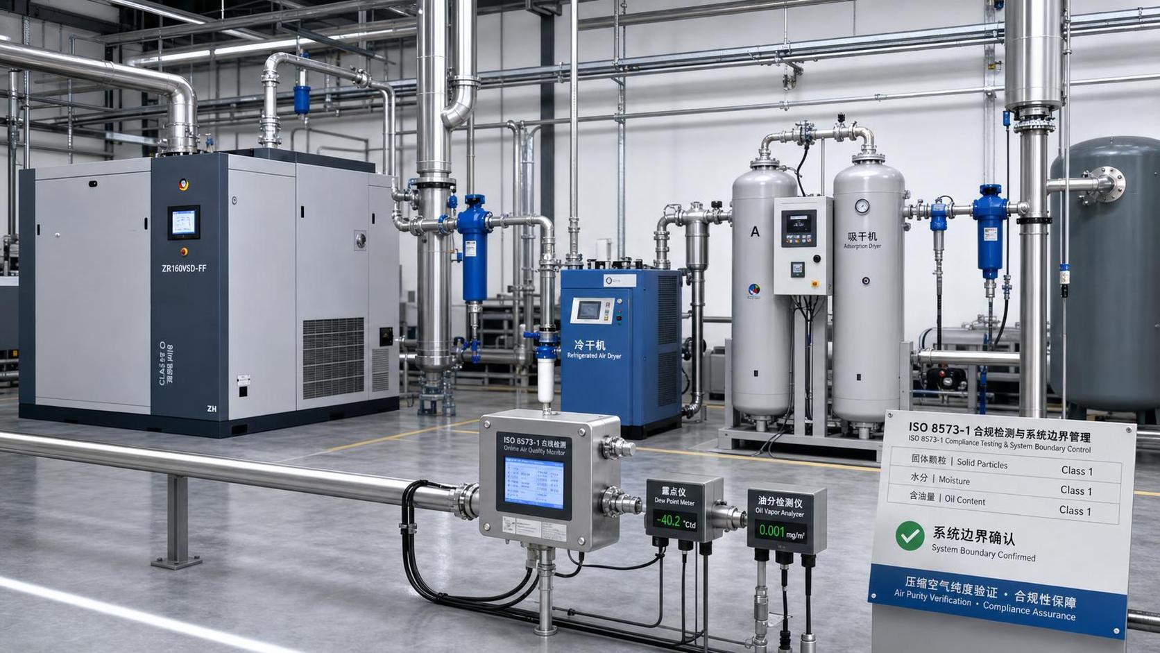
The practical answer is to verify compressed air cleanroom standards by translating the process risk into a documented air-quality requirement, then checking whether every element of the proposed system can maintain that requirement at the point of use. Start with the applicable ISO 8573 purity classes, but do not stop there. Confirm the test method, sampling locations, moisture requirement, filtration sequence, piping materials, installation controls, and acceptance criteria before equipment is installed.
Begin with the air’s actual contact risk
“Cleanroom compressed air” is not one universal grade. The required condition depends on what the air does after it leaves the outlet. Air used to operate a valve actuator outside a critical zone does not face the same risk as air used to blow-dry a component, convey an ingredient, inflate sterile packaging, or contact a product surface directly.
Before reviewing compressor brochures or filter quotations, map each intended use and assign it to one of three practical categories:
- Indirect utility air: used for pneumatic controls, cylinders, or equipment functions where air has no meaningful exposure to product, product-contact surfaces, or critical cleanroom zones.
- Process-adjacent air: discharged near open product, sensitive assemblies, clean packaging, or controlled environments. Even without direct contact, particle shedding, oil aerosol, or unexpected condensate may create an environmental risk.
- Direct-contact or critical process air: used in a way that can contact product, ingredients, sterile barriers, product-contact equipment, or surfaces that cannot be readily cleaned afterward.
This classification should be agreed by quality, safety, process engineering, and facilities personnel. It is not enough to label every outlet “cleanroom air.” That label can conceal different risks and can lead to one oversized, poorly justified specification—or a utility-grade system being used in a critical process.
Also identify what contaminant would matter most at each use point. A dry electronics process may be especially sensitive to water vapor and particles. Food or pharmaceutical operations may require strict control of oil, microorganisms, and any possibility of liquid water. A packaging line may have a different concern: odor, lubricant carryover, or fibers from hoses. The quality target must reflect the risk, not merely the cleanroom classification of the room.
Read ISO 8573 correctly before writing a requirement
ISO 8573 is widely used to describe compressed-air purity. The most commonly referenced part, ISO 8573-1, classifies contaminants in three separate categories: solid particles, water, and oil. A requirement is usually expressed as three numbers, such as particle class / water class / oil class. Each number has meaning only when its contaminant category is clear.
A frequent pre-installation error is to specify only “ISO 8573-1 Class 1.” That statement is incomplete. It does not tell the installer whether Class 1 refers to particles, water, oil, or all three. A clearer requirement identifies each category and the intended verification point, for example: “Air at designated point-of-use outlets shall meet the approved particle, water, and total-oil classes under representative operating conditions.” The exact classes should come from the process risk assessment and internal quality requirements.
Do not assume that an oil-free compressor alone proves compliance with a low oil class. Oil may enter through ambient intake air, lubricated ancillary equipment, maintenance practices, unsuitable hoses, or contamination remaining in old pipework. Similarly, a dryer rating alone does not demonstrate the dew point that will exist at a remote outlet after pressure drop, reduced flow, or exposure to colder conditions.
ISO 8573 provides a language for air purity; it does not automatically determine what purity level a specific cleanroom process needs. Nor does a cleanroom room classification by itself set a compressed-air class. Treat the air specification and the room specification as related but distinct controls.
Turn the standard into a point-of-use design basis
The design basis should state where compliance begins and ends. This is one of the most important decisions to settle before piping is ordered. An air-treatment package may meet a stated quality at its outlet, while the point of use receives different air because of contaminated distribution lines, condensate collection, pressure fluctuations, or an added hose assembly.
For critical outlets, the acceptance requirement should normally be tied to the actual point where air enters the process or the final user connection. That does not always mean every outlet must be tested identically. A sensible plan can define representative branches, critical points, and worst-case locations, provided the rationale is documented.
Confirm the operating envelope, not only the nominal flow
Ask for the system design conditions in writing: minimum and maximum flow, normal pressure, allowable pressure drop, ambient temperature range, inlet-air condition, duty cycle, and simultaneous demand. Treatment equipment can perform differently when demand is low, when a receiver is nearly empty, or when several high-flow users operate together. A cleanroom process should not rely on a purity claim established only under ideal or partial-load conditions.
Pressure changes deserve special attention. Pressure dew point and downstream temperature affect whether water remains vapor or becomes liquid. A line that appears dry near the dryer may form condensate after a pressure reduction or in a cool area. Verify that the design addresses drains, low points, separators where needed, and access for inspection. Drains must discharge safely without creating a contamination or slip hazard.
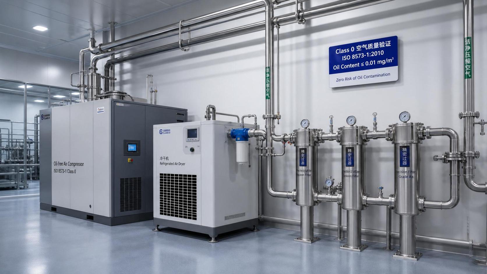
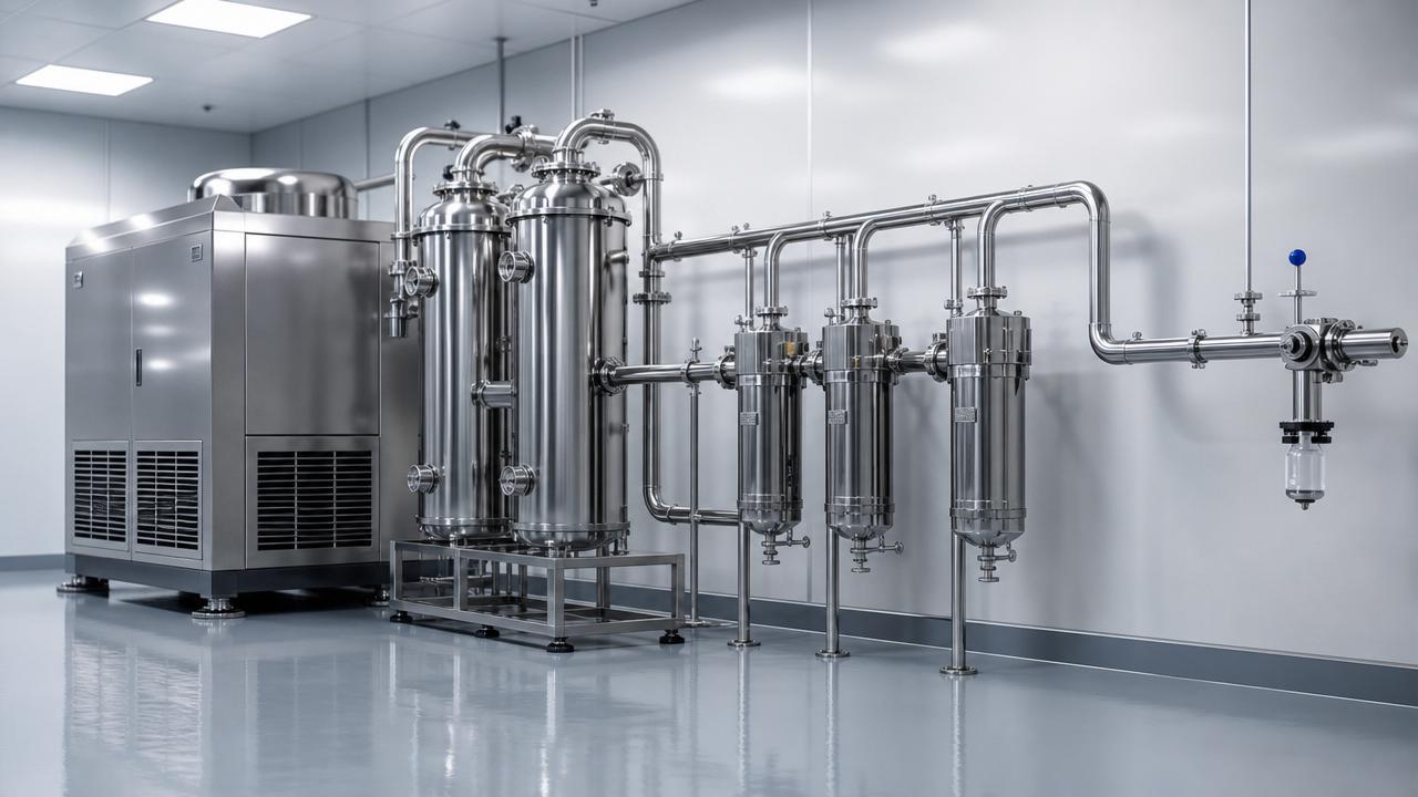
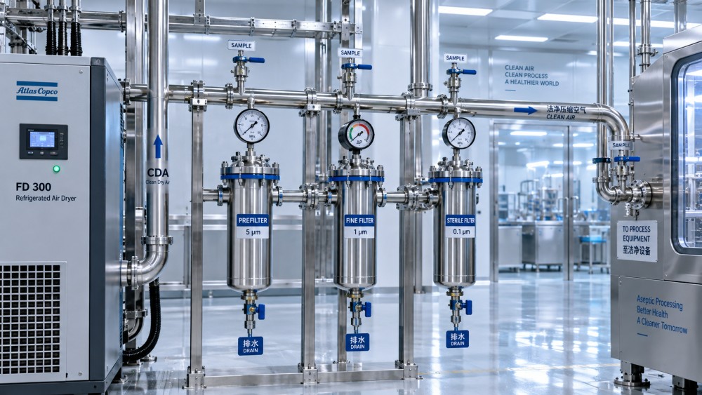
Check the filtration train as a system
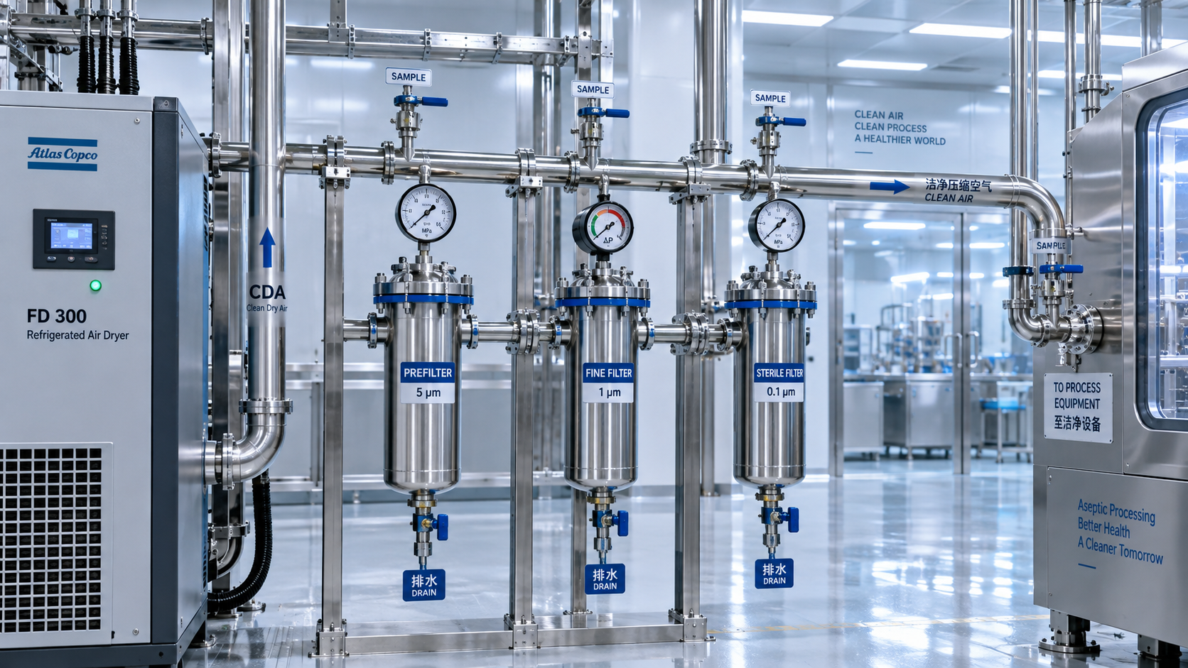
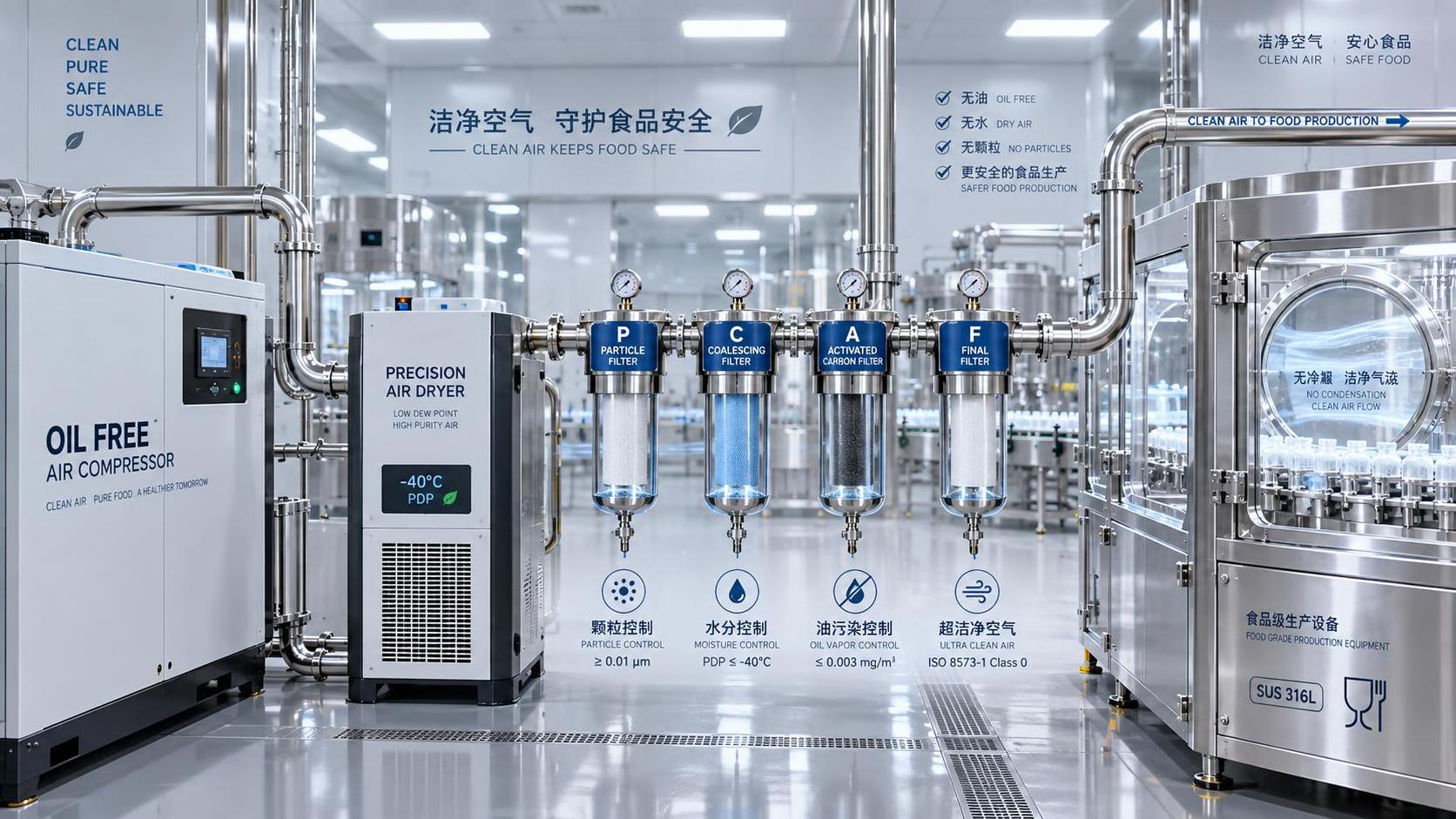
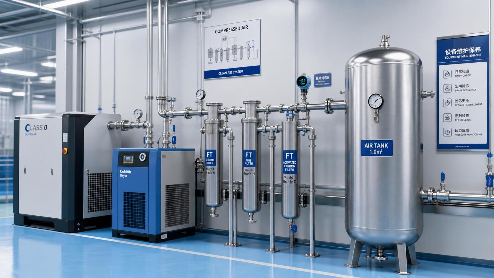
Filters should be selected in sequence, not as isolated components. Upstream particulate removal protects coalescing elements; coalescing filters capture liquid aerosols; additional treatment may be needed when extremely low oil vapor levels are specified. Each device has a pressure-drop range, service limit, and installation orientation. A technically correct filter installed backward, bypassed during servicing, or placed where condensate reaches it continuously can become a source of risk rather than control.
Review proposed filter housings, element materials, seals, differential-pressure indication, isolation valves, and bypass arrangements. In critical service, an uncontrolled bypass can defeat the entire treatment train. Decide before installation whether filters can be changed without exposing clean distribution lines to unfiltered air or maintenance debris.
Inspect the distribution network for contamination pathways
A clean air source can be compromised in the last few meters. Distribution design therefore belongs in the standard-verification review. New pipework should be assessed not only for pressure capacity and corrosion resistance, but also for internal cleanliness, joining method, dead-leg control, drainability, and compatibility with the required air purity.
Materials that corrode internally or release scale can undermine particle control. Poorly prepared threaded joints, cutting debris, inappropriate sealants, and flexible hoses with unknown internal construction can introduce particles or chemical residues. Where strict cleanliness is required, specify how pipe sections will be cut, cleaned, capped, transported, and protected from construction dust before final connection.
Look closely at locations where contamination can accumulate:
- low points without effective drainage;
- long unused branches and dead ends;
- drops taken from the bottom of a main header, where condensate can travel toward equipment;
- temporary hoses retained as permanent connections;
- quick-connect fittings that are left uncapped during maintenance;
- shared lines serving both critical and noncritical equipment without segregation.
For many installations, drops are taken from the top of a main header to reduce carryover of condensed water or debris. This does not eliminate the need for proper drainage and pipe cleaning, but it reflects a basic contamination-control principle: do not make the process outlet the easiest path for material collected in the main line.
Require evidence that matches the claim
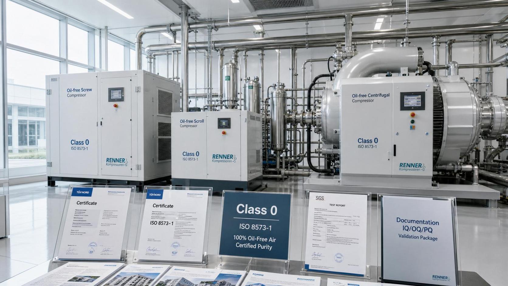
Supplier certificates, compressor data sheets, and filter performance literature are useful inputs, but they are not the same as installed-system verification. Before installation, define what evidence will be acceptable at commissioning. The plan should distinguish between component qualification and system acceptance.
Component documentation may confirm pressure ratings, stated filtration performance, materials, and recommended maintenance intervals. Installed-system acceptance should demonstrate that the assembled system meets its approved requirement under representative conditions. This includes commissioning after pipework cleaning and before routine cleanroom use.
A workable verification package usually identifies the following:
- Approved air-quality specification: particle, water, and oil targets, plus any process-specific controls such as microbiological monitoring where justified by the application.
- Sampling plan: sampling points, representative outlets, worst-case branches, operating state, required stabilization time, and precautions against contaminating samples.
- Test method and equipment: methods appropriate to the contaminant being measured, suitable measurement range, calibration status, and defined reporting units.
- Acceptance and response rules: pass/fail criteria, investigation requirements, retest conditions, and authority to release the system for use.
- Traceable records: installation drawings, filter and dryer identification, test reports, pressure readings, maintenance baseline, and any deviations closed before release.
Sampling is particularly easy to get wrong. A sample taken immediately downstream of the treatment skid may show excellent results while a distant process outlet does not. Conversely, a poorly connected sampling device can create false particle or moisture readings. The method should specify clean sampling connections, appropriate flow control, and sampling after the system has reached a representative operating condition.
Do not overlook microbial and hygienic controls
ISO 8573 classifications are central to particle, water, and oil control, but they do not replace a hygienic risk assessment. Where compressed air can contact a sensitive product or sterile barrier, quality teams may need additional controls addressing microorganisms, endotoxins, odor, or other contaminants relevant to their process. The appropriate controls depend on the product, exposure route, cleaning strategy, and governing internal or regulatory requirements.
It is risky to add a sterilizing final filter simply because the word “cleanroom” appears in the project scope. A final filter must be compatible with pressure, flow, cleaning or replacement practice, integrity expectations where applicable, and the risk of moisture accumulation upstream. In some applications, a sterile filter is essential; in others, it may be unnecessary or may create maintenance challenges without addressing the actual contamination route. Document why it is included, where it is located, and how it will be maintained.
Use installation controls to protect a compliant design
Even a well-designed system can be compromised during construction. Include compressed air in the cleanroom installation-control plan rather than treating it as ordinary utility piping. Lines should remain capped when open. Pipe interiors should be protected from grinding dust, debris, insects, moisture, and cleaning chemicals. Temporary construction air should not be connected to finished critical branches unless its quality and connection controls are approved.
Before final commissioning, verify that labels match the approved drawings and that critical outlets cannot be confused with general plant air. Confirm flow direction, drain locations, isolation points, filter orientation, alarm connections, and access for service. Maintenance access matters because a filter that cannot be changed cleanly will eventually be changed unsafely.
Finally, establish the baseline that will support ongoing control. Record initial pressure dew point, differential pressures, outlet pressure, and verified air-quality results. Define what operational changes trigger reassessment: a compressor replacement, added demand, dryer alarm, recurring condensate, pipework modification, or altered process use. Compressed air cleanroom standards are verified before installation, but they remain reliable only when the original design basis is preserved through operation and change control.
Related News
- How to verify compressed air cleanroom standards before installationAuthor :Pneumatic Power Engineer

- When oil free vacuum pumps make sense for European cleanroom projectsAuthor :Pneumatic Power Engineer

- When do pure air compression systems need ISO 8573-1 Class 0?Author :Pneumatic Power Engineer

- How do compressed air systems for electronics prevent contamination?Author :Pneumatic Power Engineer

- When does an oil-free process vacuum pump justify its higher cost?Author :Pneumatic Power Engineer

- Does ISO 9001 certification apply to compressed air quality?Author :Pneumatic Power Engineer

- How to Specify Clean Compressed Air Systems in Southeast Asia for Food and Pharma PlantsAuthor :Pneumatic Power Engineer

- How to Compare Oil Free Vacuum Pumps for Clean Process RequirementsAuthor :Pneumatic Power Engineer

- How to Evaluate a Clean Compressed Air Systems Supplier for ISO 8573-1 ComplianceAuthor :Pneumatic Power Engineer

- How to Choose the Right Oil-Free Vacuum PumpAuthor :Pneumatic Power Engineer

- VDI 2083 Update Makes Class 0 Proof MandatoryAuthor :Pneumatic Power Engineer

- When to Use Oil Free Vacuum Pumps for High Purity LinesAuthor :Pneumatic Power Engineer

- Compressed Air Solutions: When Oil-Free Systems Lower Total Operating CostAuthor :Pneumatic Power Engineer

- ATMOsphere Europe 2026 Adds Oil-free Systems ZoneAuthor :Pneumatic Power Engineer

- Oil-Free Compressors: Key Selection Criteria for Clean Air SystemsAuthor :Pneumatic Power Engineer

- How to Compare Oil Free Centrifugal Compressors for Stable Plant Air SupplyAuthor :Pneumatic Power Engineer

- Compressed Air Class 0 vs Oil-Free: What Really MattersAuthor :Pneumatic Power Engineer

- Oil-Free Compression Class 0: What the Standard Really Means in ProductionAuthor :Pneumatic Power Engineer

- Air Compression Cost Comparison: Oil-Free vs Screw Systems in Daily OperationAuthor :Pneumatic Power Engineer

- Saudi SASO Tightens IEC 63349-2 for Oil-Free CompressorsAuthor :Pneumatic Power Engineer

- Saudi SASO Tightens Oil-Free Compressor Efficiency RulesAuthor :Pneumatic Power Engineer

- Pure Air Compression Systems for Clean Production LinesAuthor :Pneumatic Power Engineer

- IEC 63349-2:2026 makes energy certification mandatoryAuthor :Pneumatic Power Engineer

- IEC 63349-2:2026 Sets New Entry Rules for Oil-Free Screw CompressorsAuthor :Pneumatic Power Engineer

- IEC 63349-2:2026 Takes Effect for Oil-Free Screw CompressorsAuthor :Pneumatic Power Engineer

- IEC 63349-2:2026 Sets New Efficiency Gate for Oil-Free Screw CompressorsAuthor :Pneumatic Power Engineer

- IEC 63349-2:2026 Takes Effect for Oil-Free Screw CompressorsAuthor :Pneumatic Power Engineer

- SABIC Methanol Force Majeure Extended, Tightening R134a/R407C FeedstocksAuthor :Pneumatic Power Engineer

- How to Evaluate Pneumatic Power Systems for Stable OutputAuthor :Pneumatic Power Engineer

- Oil-Free Compression vs Lubricated Systems: Key Trade-OffsAuthor :Pneumatic Power Engineer
![]()
- Oil-Free Compression: 2026 Cost and Compliance Trade-OffsAuthor :Pneumatic Power Engineer

- Oil-Free Compression: Cost and Contamination RisksAuthor :Pneumatic Power Engineer
![]()
- Euro PMI Drop Delays Oil-Free Systems OrdersAuthor :Pneumatic Power Engineer

- Germany/France May PMI Decline; Oil-free Systems EU Projects DelayedAuthor :Pneumatic Power Engineer
![]()
- Compression Technology Options for Cleaner Oil-Free Air SupplyAuthor :Pneumatic Power Engineer

- TUV Rheinland Enforces Full-Chain Class 0 Certification for Oil-Free SystemsAuthor :Pneumatic Power Engineer