



How to size oil-free compressors for instrumentation air demand




Instrumentation air should be sized from the air actually required at the point of use, not from the nominal capacity of existing compressors or a simple sum of connected device catalog values. In critical pneumatic control systems, undersizing shows up as pressure collapse during valve movement, poor analyzer performance, unstable positioners, or compressor operation at an inefficient and unreliable loading point. Oversizing can be equally damaging when it produces excessive unloaded running, poor moisture management, and avoidable capital cost.
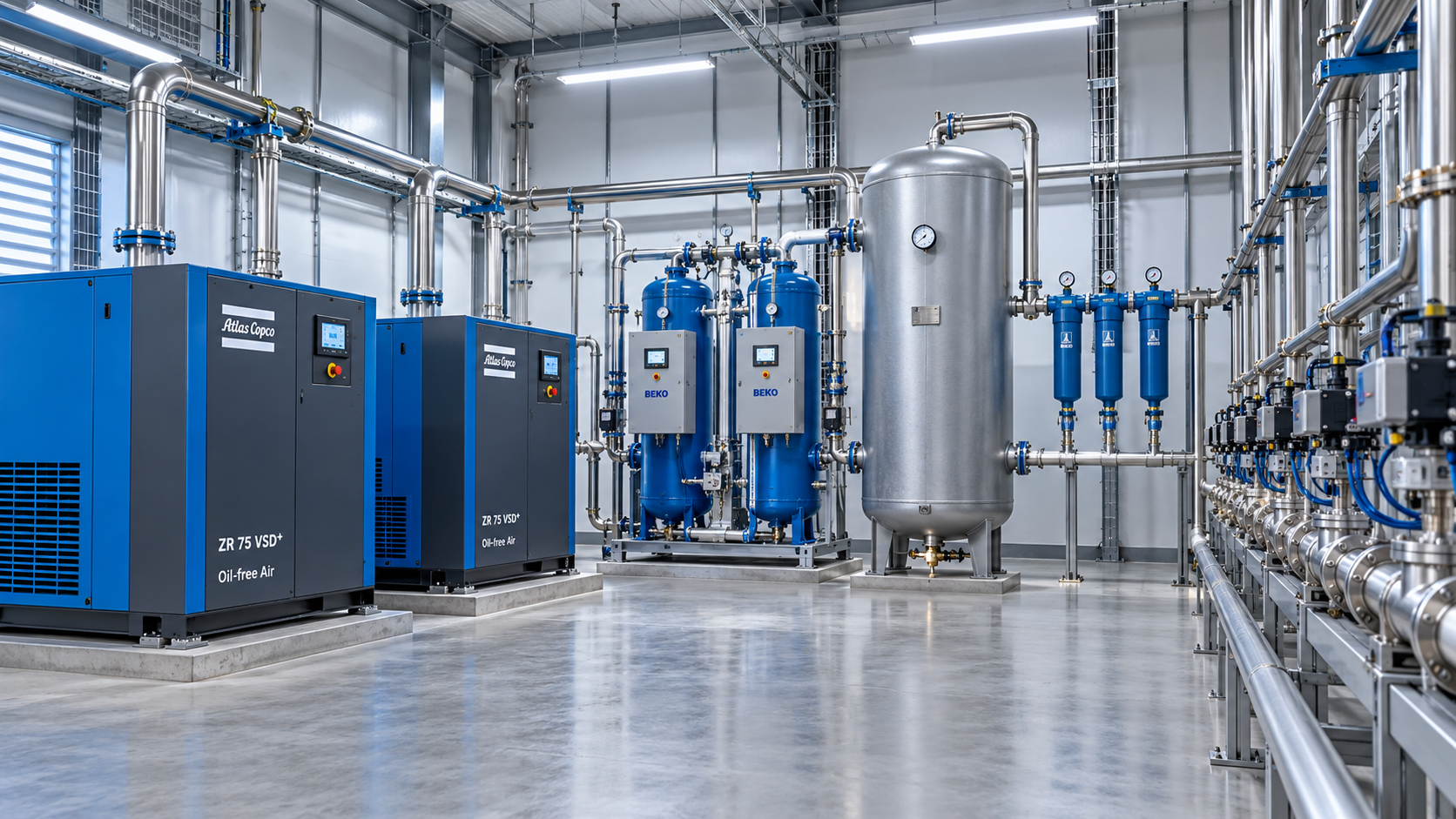
For oil-free compressors for instrumentation, the capacity calculation must connect five separate questions: how much air instruments consume in steady operation; how much is released in short peaks; what pressure must remain available at remote users; what air quality must be maintained; and how the system will operate when a compressor, dryer, or utility connection is unavailable. The compressor is only one part of that calculation.
Start with a demand boundary, not a compressor nameplate
The first technical decision is to define exactly what belongs on the instrumentation-air header. This often includes control-valve actuators and positioners, pneumatic solenoids, analyzer purges, pneumatic relays, air-operated dampers, instrument enclosures, panel purges, and local maintenance outlets if they are intentionally connected to the same system. Plant air users such as blow guns, diaphragm pumps, bag filters, and general cleaning stations should not be quietly included unless the header is designed to support them. Their intermittent but high demand can distort an instrument-air system that was intended to be stable and clean.
Each listed consumer needs a demand basis. Device literature may state consumption in NL/min, SCFM, Nm³/h, or free-air volume per stroke. These are not interchangeable unless the reference temperature, pressure, and humidity basis are known. Compressor ratings are commonly expressed as free air delivery (FAD), but the stated reference conditions and allowable tolerance must be read in the manufacturer’s documentation. A calculation that mixes actual compressed volume at line pressure with standard-condition flow will produce a false result.
For each continuous user, record normal consumption and any higher mode of operation. A pneumatic positioner, for example, may have modest steady-state bleed but much higher demand when responding to a process upset. For each discrete actuator, record the volume needed for a full stroke, the required stroking time, whether opening and closing consume the same volume, and the probability that multiple devices move together.
The basic steady-demand equation is:
Qbase = Σ Qcontinuous + Σ Qaverage intermittent + Qpurge + Qknown losses
All terms should be converted to one standard volumetric basis before they are added. Average intermittent demand is useful for compressor energy sizing, but it is not sufficient for pressure-stability design.
Separate average demand from transient demand
Instrumentation systems rarely draw air as a perfectly smooth load. A process shutdown, emergency sequence, changeover, or control response can command many actuators at once. A compressor sized only to average air use may have enough daily capacity yet still fail to preserve header pressure during a brief high-demand event.
The correct question is not “How many actuators are installed?” but “Which actuators can legitimately stroke within the same time window?” The answer should come from process logic, cause-and-effect charts, shutdown philosophy, and control narratives. Summing every actuator at full-stroke demand assumes a simultaneous event that may never occur; applying an arbitrary diversity factor assumes the opposite without evidence. Both approaches are weak.
For a defined event, calculate the required free-air volume:
Vevent = Σ (Vstroke × number of strokes expected during the event)
Then compare that requirement with the usable air stored in receivers and the air supplied by operating compressors during the event. Receiver sizing is especially important when peak duration is shorter than the compressor response time or when a variable-speed machine is operating near its minimum stable capacity.
The usable free-air equivalent from a receiver depends on receiver volume, initial and minimum acceptable absolute pressure, and the selected standard pressure basis. In practical terms, a receiver does not provide its full geometric volume as usable air. The available pressure swing is limited by the lowest pressure at which downstream regulators, positioners, and actuators can still meet their functional requirements.
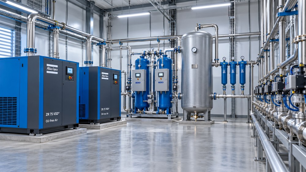
A useful sizing model therefore has two layers:
- Compressor flow capacity must cover sustained demand, the intended recharge rate after a transient, dryer and drain-related losses where applicable, and a justified allowance for future load.
- Receiver capacity must bridge short-duration events without allowing header pressure to fall below the minimum operating limit.
Using compressor capacity to cover every momentary peak can result in an unnecessarily large machine. Using receiver storage to mask a persistent demand deficit creates long recovery times and recurring low-pressure alarms. The two functions should be evaluated together.
Pressure is a system requirement, not a single setpoint
Required discharge pressure should be established backward from the most demanding point of use. Begin with the minimum pressure needed at the actuator or instrument under its worst credible load. Add the local regulator requirement, filter differential pressure at end-of-life condition, distribution-pipe losses at peak flow, isolation-valve and fitting losses, dryer and treatment losses, and a reasonable control band for compressor sequencing.
This produces a pressure budget rather than a nominal header number. A system set at 7 barg may appear adequate until filter loading, peak flow, or a long branch line reduces remote pressure by enough to impair valve stroking. Raising compressor discharge pressure to compensate for poor distribution design increases energy use and may not resolve a localized restriction.
Pressure drop should be assessed at the actual peak flow and anticipated future configuration, not only at normal operation. Long small-bore branches, restrictive quick couplings, undersized coalescing filters, and regulators selected for average rather than peak Cv are frequent sources of hidden pressure loss. The required pressure at an actuator may also differ between holding position and completing a rapid fail-safe or process stroke.
Compression ratio matters as well. A compressor selected at a higher pressure than the distribution system truly needs will consume more power and may produce more heat for the dryer to remove. Conversely, selecting a machine whose rated flow is quoted at a lower pressure than the required discharge condition can create an apparent capacity margin that does not exist in service.
Oil-free compression does not eliminate air-treatment design
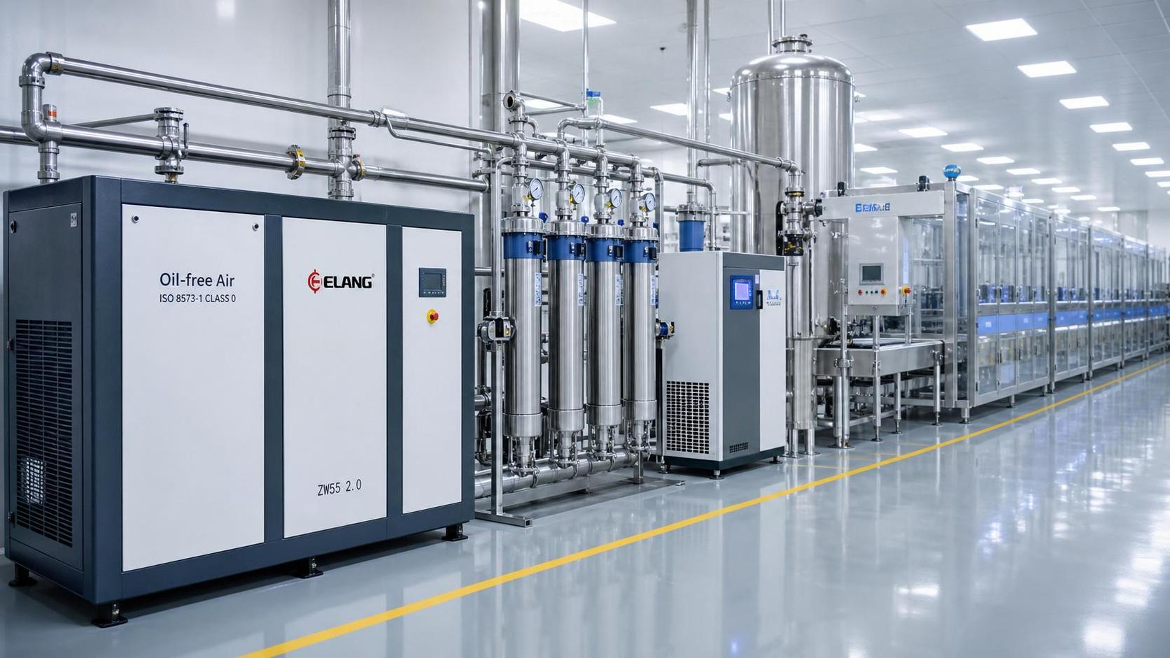
Oil-free technology is often selected because instrument air must avoid hydrocarbon contamination that can damage pneumatic components, interfere with analytical equipment, or compromise sensitive processes. That choice addresses a major contamination source, but it does not establish the delivered air-quality class by itself.
Ambient intake air contains water vapor, particles, and potentially oil aerosols or vapors from the surrounding environment. Internal corrosion, piping debris, desiccant dust, and microbial concerns in certain applications are separate issues. An oil-free compressor may also require cooling water quality, intake filtration, and maintenance practices that affect reliability even though no lubricating oil is introduced into the compression chamber.
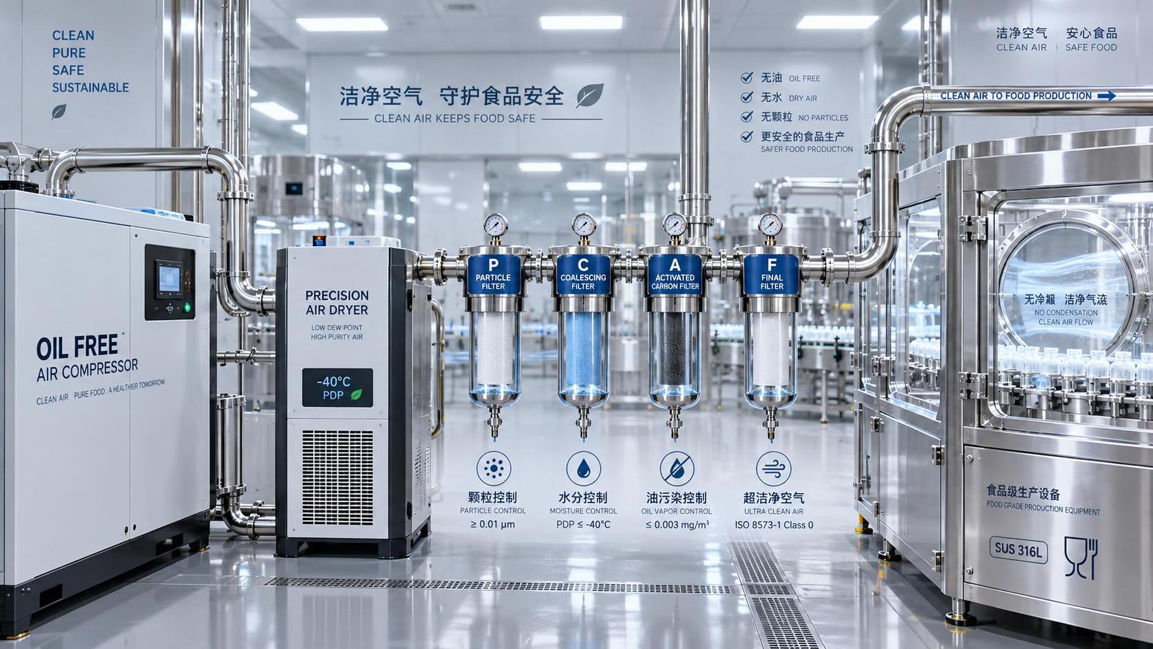
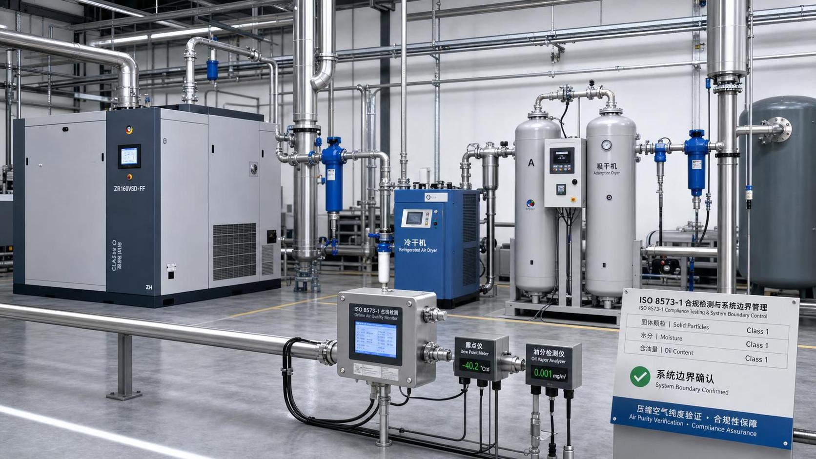
Air-quality requirements should be written at the point of use, using the relevant ISO 8573-1 classes for particles, water, and oil where that standard is specified by the project or end user. The three classes should be defined independently. A statement such as “ISO 8573-1 Class 1” is incomplete because the standard expresses air purity through separate particle, water, and oil class designations.
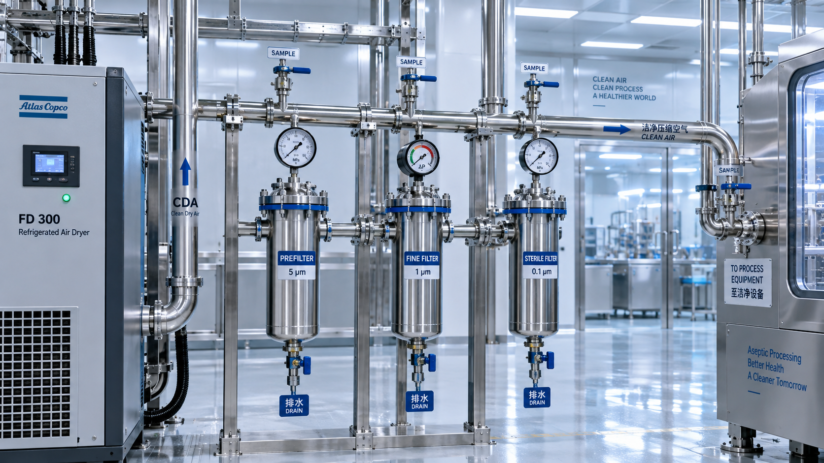
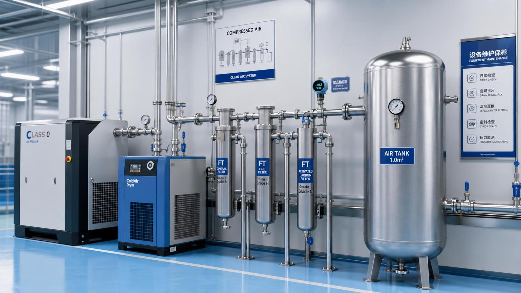
For instrumentation, water is often the decisive design variable. Dew point must remain below the lowest temperature that the air system will experience, including outdoor pipe runs, unheated shelters, or cold-start conditions. A refrigerated dryer may be suitable where the required pressure dew point and ambient conditions permit it. Where low dew point is required, a heatless, heated purge, or blower-purge desiccant dryer may be necessary. Those dryer types differ materially in purge-air consumption, electrical demand, regeneration behavior, and performance sensitivity.
Dryer purge air is not an incidental detail. If a heatless desiccant dryer uses compressed air for regeneration, that consumption must be included in compressor capacity at the actual operating pressure and duty cycle. The same applies to controls, drains, and any continuous purge consumers. Excluding these loads can turn a seemingly adequate compressor into a chronic capacity shortfall.
Allow for leakage only after finding and classifying it
Leakage is common in compressed-air systems, but it should not be treated as a permanent design feature. A measured leakage load may need to be covered initially to avoid operational risk, especially in an existing plant, yet the sizing file should distinguish between unavoidable operating demand and correctable loss.
A practical way to establish leakage is to isolate normal consumers during a controlled quiet period and observe the compressed-air flow or compressor load after receiver pressure has stabilized. This test must account for dryers, automatic drains, purge systems, and any instruments that cannot be isolated. The result should be documented as a baseline and paired with a leak-reduction action, not hidden inside a large generic design margin.
Large unquantified margins are a poor substitute for load characterization. They can lead to excessive installed flow, more cycling in fixed-speed compressors, and a system that wastes energy for its entire life. A defined expansion allowance is different: it should be tied to approved additional instruments, a known process phase, reserved analyzer connections, or a planned production train.
Size redundancy around the required duty, not installed nameplate flow
Instrumentation air frequently supports process safety and control continuity, so redundancy must be evaluated at the system level. “Two compressors installed” does not automatically mean N+1 capability. If each compressor can only satisfy normal demand under ideal inlet and discharge conditions, loss of one machine leaves no capacity for peak demand, dryer purge, leakage, or recovery after a stored-air event.
Define the required duty capacity as the flow needed during the stated design case at the required pressure and environmental conditions. Then verify that the remaining compressor configuration can meet that duty after one relevant failure or maintenance outage. The relevant failure may be a compressor, dryer train, power supply, cooling-water circuit, or common control element, depending on the architecture.
Redundancy should also be checked below the compressor package. Common headers without isolation, a single undersized dryer, a shared drain failure, or one nonmaintainable final filter can negate compressor redundancy. For critical systems, switching arrangements must avoid exposing the header to a pressure or dew-point excursion during changeover.
Where standby capacity is required, a duty/standby rotation strategy helps prevent one machine from remaining idle for long periods. However, automatic sequencing should not cause frequent starts, unstable sharing, or repeated loading and unloading at low demand. The preferred control philosophy depends on the compressor type, available turndown, receiver volume, and the ratio of minimum to maximum demand.
Correct rated capacity for actual site conditions
Compressor performance must be checked at the project site, not merely against a brochure rating. Higher inlet temperature reduces mass flow available from a given displacement machine and increases compression work. Altitude reduces inlet air density. Elevated cooling-water or ambient temperatures can constrain air-cooled or water-cooled package performance. Required discharge pressure, inlet filter condition, and allowable motor margin also affect delivered capacity.
Request a performance curve or guaranteed FAD at the specified inlet temperature, site elevation, relative humidity basis where relevant, and discharge pressure. For packaged oil-free compressors, confirm whether the stated flow includes all internal losses and whether capacity control changes at the selected pressure. A quoted maximum flow at one condition is not necessarily the usable flow across the project operating envelope.
Electrical supply is another boundary condition. Motor starting method, harmonic constraints for variable-speed drives, emergency power availability, and restart logic after a power interruption can matter more to instrument-air availability than a small difference in nominal flow.
Evaluate the operating envelope before choosing control type
A fixed-speed oil-free compressor can be appropriate where demand is stable and a properly sized receiver smooths normal fluctuations. A variable-speed unit can better follow a changing base load, but it is not automatically the most efficient answer. Every machine has a practical operating range, and efficiency can deteriorate below a certain turndown point. If demand regularly falls below that point, the system may cycle, vent, or rely on another machine to maintain stable pressure.
For broad demand variation, the selection should compare the expected demand profile against the compressor’s specific power curve, minimum flow limit, receiver strategy, and sequencing logic. The aim is not simply to maximize turndown; it is to maintain pressure and air quality with the lowest stable lifecycle burden. In a critical instrument-air application, stable control and maintainability should take priority over theoretical efficiency gains that depend on narrow operating assumptions.
The final sizing document should make assumptions visible
A defensible selection package identifies every load, its unit basis, normal and peak condition, simultaneity assumption, minimum point-of-use pressure, pressure-drop allowance, dryer technology, quality target, purge consumption, leakage basis, site correction, and redundancy case. It should also state how quickly the receiver must recover after the governing transient event.
The resulting compressor capacity is not merely a number in SCFM or Nm³/h. It is a verified ability to supply clean, dry, stable air at the required pressure during normal operation, credible process events, maintenance conditions, and expected expansion. That distinction is what separates a correctly sized oil-free instrumentation-air system from one that only appears adequate on a datasheet.
Related News
- How to size oil-free compressors for instrumentation air demandAuthor :Pneumatic Power Engineer

- How Class 0 oil-free compressors protect product quality in food productionAuthor :Pneumatic Power Engineer

- How to verify compressed air cleanroom standards before installationAuthor :Pneumatic Power Engineer

- When oil free vacuum pumps make sense for European cleanroom projectsAuthor :Pneumatic Power Engineer

- When do pure air compression systems need ISO 8573-1 Class 0?Author :Pneumatic Power Engineer

- How do compressed air systems for electronics prevent contamination?Author :Pneumatic Power Engineer

- When does an oil-free process vacuum pump justify its higher cost?Author :Pneumatic Power Engineer

- Does ISO 9001 certification apply to compressed air quality?Author :Pneumatic Power Engineer

- How to Specify Clean Compressed Air Systems in Southeast Asia for Food and Pharma PlantsAuthor :Pneumatic Power Engineer

- How to Compare Oil Free Vacuum Pumps for Clean Process RequirementsAuthor :Pneumatic Power Engineer

- How to Evaluate a Clean Compressed Air Systems Supplier for ISO 8573-1 ComplianceAuthor :Pneumatic Power Engineer

- How to Choose the Right Oil-Free Vacuum PumpAuthor :Pneumatic Power Engineer

- VDI 2083 Update Makes Class 0 Proof MandatoryAuthor :Pneumatic Power Engineer

- When to Use Oil Free Vacuum Pumps for High Purity LinesAuthor :Pneumatic Power Engineer

- Compressed Air Solutions: When Oil-Free Systems Lower Total Operating CostAuthor :Pneumatic Power Engineer

- ATMOsphere Europe 2026 Adds Oil-free Systems ZoneAuthor :Pneumatic Power Engineer

- Oil-Free Compressors: Key Selection Criteria for Clean Air SystemsAuthor :Pneumatic Power Engineer

- How to Compare Oil Free Centrifugal Compressors for Stable Plant Air SupplyAuthor :Pneumatic Power Engineer

- Compressed Air Class 0 vs Oil-Free: What Really MattersAuthor :Pneumatic Power Engineer

- Oil-Free Compression Class 0: What the Standard Really Means in ProductionAuthor :Pneumatic Power Engineer

- Air Compression Cost Comparison: Oil-Free vs Screw Systems in Daily OperationAuthor :Pneumatic Power Engineer

- Saudi SASO Tightens IEC 63349-2 for Oil-Free CompressorsAuthor :Pneumatic Power Engineer

- Saudi SASO Tightens Oil-Free Compressor Efficiency RulesAuthor :Pneumatic Power Engineer

- Pure Air Compression Systems for Clean Production LinesAuthor :Pneumatic Power Engineer

- IEC 63349-2:2026 makes energy certification mandatoryAuthor :Pneumatic Power Engineer

- IEC 63349-2:2026 Sets New Entry Rules for Oil-Free Screw CompressorsAuthor :Pneumatic Power Engineer

- IEC 63349-2:2026 Takes Effect for Oil-Free Screw CompressorsAuthor :Pneumatic Power Engineer

- IEC 63349-2:2026 Sets New Efficiency Gate for Oil-Free Screw CompressorsAuthor :Pneumatic Power Engineer

- IEC 63349-2:2026 Takes Effect for Oil-Free Screw CompressorsAuthor :Pneumatic Power Engineer

- SABIC Methanol Force Majeure Extended, Tightening R134a/R407C FeedstocksAuthor :Pneumatic Power Engineer

- How to Evaluate Pneumatic Power Systems for Stable OutputAuthor :Pneumatic Power Engineer

- Oil-Free Compression vs Lubricated Systems: Key Trade-OffsAuthor :Pneumatic Power Engineer
![]()
- Oil-Free Compression: 2026 Cost and Compliance Trade-OffsAuthor :Pneumatic Power Engineer

- Oil-Free Compression: Cost and Contamination RisksAuthor :Pneumatic Power Engineer
![]()
- Euro PMI Drop Delays Oil-Free Systems OrdersAuthor :Pneumatic Power Engineer

- Germany/France May PMI Decline; Oil-free Systems EU Projects DelayedAuthor :Pneumatic Power Engineer
![]()