


How oil-free compressed air helps prevent printing defects




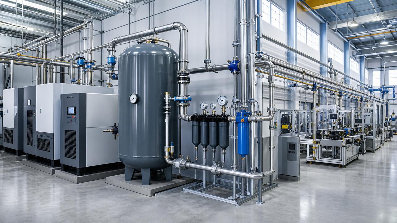
Oil-free compressed air helps prevent printing defects by removing compressor lubricant from the air compression process. Where air touches a substrate, printing plate, blanket, inked surface, or finished sheet, this reduces one potential source of oil films and droplets that can interfere with wetting and adhesion. The strongest protection comes from controlling the complete air path: intake air, compressor, dryer, distribution pipework, filters, and the point where air reaches the product.
Cleaner air does not automatically make every print defect disappear. Moisture, particles, residual oil in old pipework, and contaminants drawn into the compressor intake can still reach a press. For compressed air for printing, the useful question is therefore whether air at each critical point of use is clean and dry enough for the specific substrate, ink, and process.
Where compressed air meets the printed surface
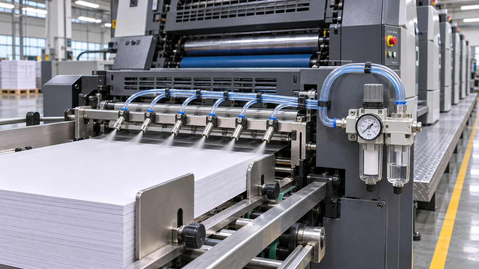
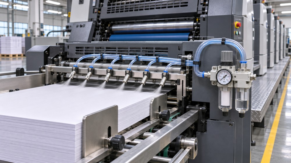
Compressed air performs several jobs around a press. It separates and transports sheets, blows dust from substrates, clears components, and operates pneumatic controls. These uses do not expose the product to the same contamination risk.
Air directed across an unprinted film immediately before ink application has little opportunity for a contaminant to be removed before printing. Oil deposited there can change local surface wetting, contributing to craters, pinholes, uneven coverage, or poor adhesion. A sheet-separation nozzle presents a different exposure: the air jet may touch the sheet edges or faces before they enter the press, and contaminants can transfer between sheets in a stack.
Blow-off after printing also deserves attention. Air that contacts a fresh ink or coating layer can deposit contamination on a surface that has not fully set. On laminated work, an oil film introduced before adhesive application can compromise the bond even when the printed image initially looks acceptable. The effect depends on where the air lands and what happens to that surface next.
Air used only inside a closed pneumatic actuator has a more indirect relationship with print quality. However, exhaust air released near an exposed web or sheet stack can create an unwanted path to the product. Mapping supply and exhaust points helps distinguish air that merely powers equipment from air that actually reaches a critical surface.
Recognizing oil-related defects without guessing
Oil contamination can produce small areas where ink or coating pulls back, leaving a crater or an unprinted spot. It can also appear as streaks, smears, localized gloss differences, or areas that fail an adhesion test. The same symptoms can arise from other causes: substrate additives, silicone transfer, cleaning residue, dust, incorrect surface treatment, ink formulation, or excessive moisture. A visual defect alone does not identify the contaminant.
Location and timing offer better clues. A repeated mark at a fixed position may point toward a roller, blanket, plate, or mechanical contact. A more scattered pattern that follows an air-blow zone makes the air stream worth investigating. Defects that appear after a compressor changeover, filter service, or period of heavy air demand can provide useful leads, but the timing still needs confirmation.
Compare affected and unaffected material from the same job where possible. Record the substrate lot, ink and coating system, press conditions, air outlets in use, and the point in the run when the defect appeared. Retain samples before cleaning the equipment or changing several settings at once. If production conditions permit, an isolated comparison with the suspect air jet disabled or supplied from a verified clean source can help narrow the cause. Any substitute supply must meet the machine’s pressure and safety requirements.
Adhesion testing should use a method appropriate to the product and its agreed acceptance criteria. Surface inspection and adhesion results are more informative when linked to air-quality measurements at the relevant outlet; neither a clean-looking filter nor an odor-free air stream establishes that the delivered air is free of contamination.
What an oil-free compressor changes
In an oil-free compressor, the compression chamber is designed so that lubricating oil is not introduced into the air being compressed. This removes a potential source of oil carryover associated with an oil-lubricated compression stage. Some oil-free machines still use lubricants in bearings or gearboxes separated from the air path, so the machine design and maintenance condition remain relevant.
Oil-free compression does not guarantee that the delivered air contains no oil. The intake can draw in oil vapor or aerosols from the surrounding environment, and downstream pipework may retain deposits from an earlier oil-lubricated system. A shared receiver, bypass line, or temporary hose can introduce contamination after the compressor. The compressor description therefore cannot substitute for a requirement at the point of use.
A properly maintained oil-lubricated compressor with suitable downstream treatment can also supply air to demanding applications. The distinction is that its treatment system must manage oil introduced during compression as well as contamination from elsewhere. Evaluating either arrangement requires evidence of delivered air quality under the operating conditions that matter to the press.
Build the air treatment around the exposure
Start at the most sensitive contact point and work upstream. Identify whether the air reaches bare substrate, a freshly printed surface, an adhesive layer, or only machine components. Then define the required limits for oil, water, and particles in terms that can be measured at that location. A single plant-wide specification may be unnecessarily strict for pneumatic controls while still failing to protect a critical blow-off nozzle if local piping is contaminated.
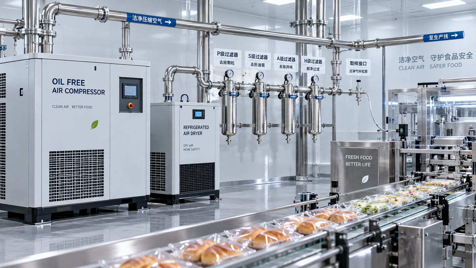
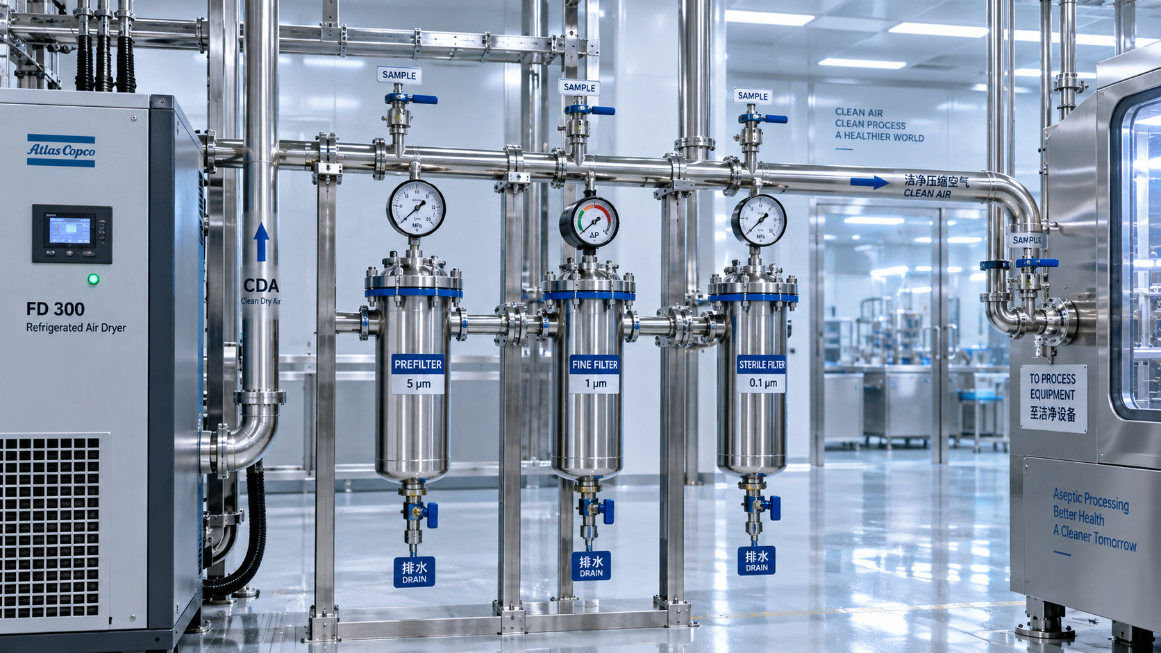
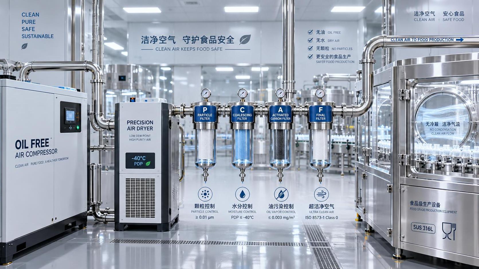
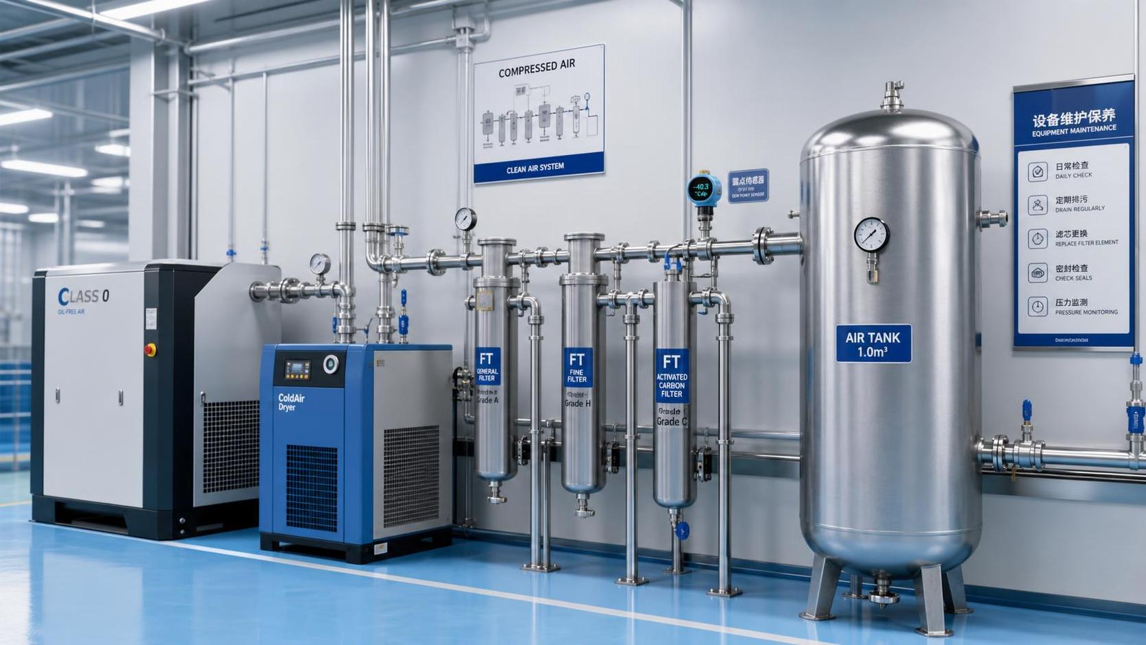
Filtration has different jobs. A particulate filter captures solid debris; a coalescing filter removes liquid aerosols; and an adsorption stage can reduce oil vapor when correctly selected and maintained. These stages are not interchangeable. A coalescing filter does not provide reliable control of oil vapor, while an adsorption medium can be overwhelmed or damaged by liquid contamination if upstream separation is inadequate. Filter selection also has to account for flow, pressure drop, temperature, and the manufacturer’s specified inlet conditions.
Water control is equally relevant to print consistency. Liquid water can carry contamination through the system and leave spots or interfere with ink and coating behavior. A dryer reduces water vapor, while separators, drains, and appropriate piping help remove liquid condensate. Select the pressure dew point with the lowest expected downstream air temperature in mind: if pipework cools below the delivered air’s pressure dew point, condensation can form after the dryer.
A refrigerated dryer may be suitable where downstream temperatures remain comfortably above its achievable pressure dew point. Colder distribution routes or more sensitive applications can require a lower dew point and a different drying approach. Measure dew point at the relevant pressure and location; a reading taken near a warm compressor does not by itself prove that a cold branch line remains dry.
Place final treatment close enough to a critical outlet to limit contamination from downstream piping, while allowing access for maintenance and sampling. New filters cannot clean a contaminated hose or nozzle installed after them. When replacing an oil-lubricated compressor, inspect the receiver and distribution network, including low points and dead legs, before assuming that the old oil source has been eliminated.
Turn air quality into a measurable acceptance condition
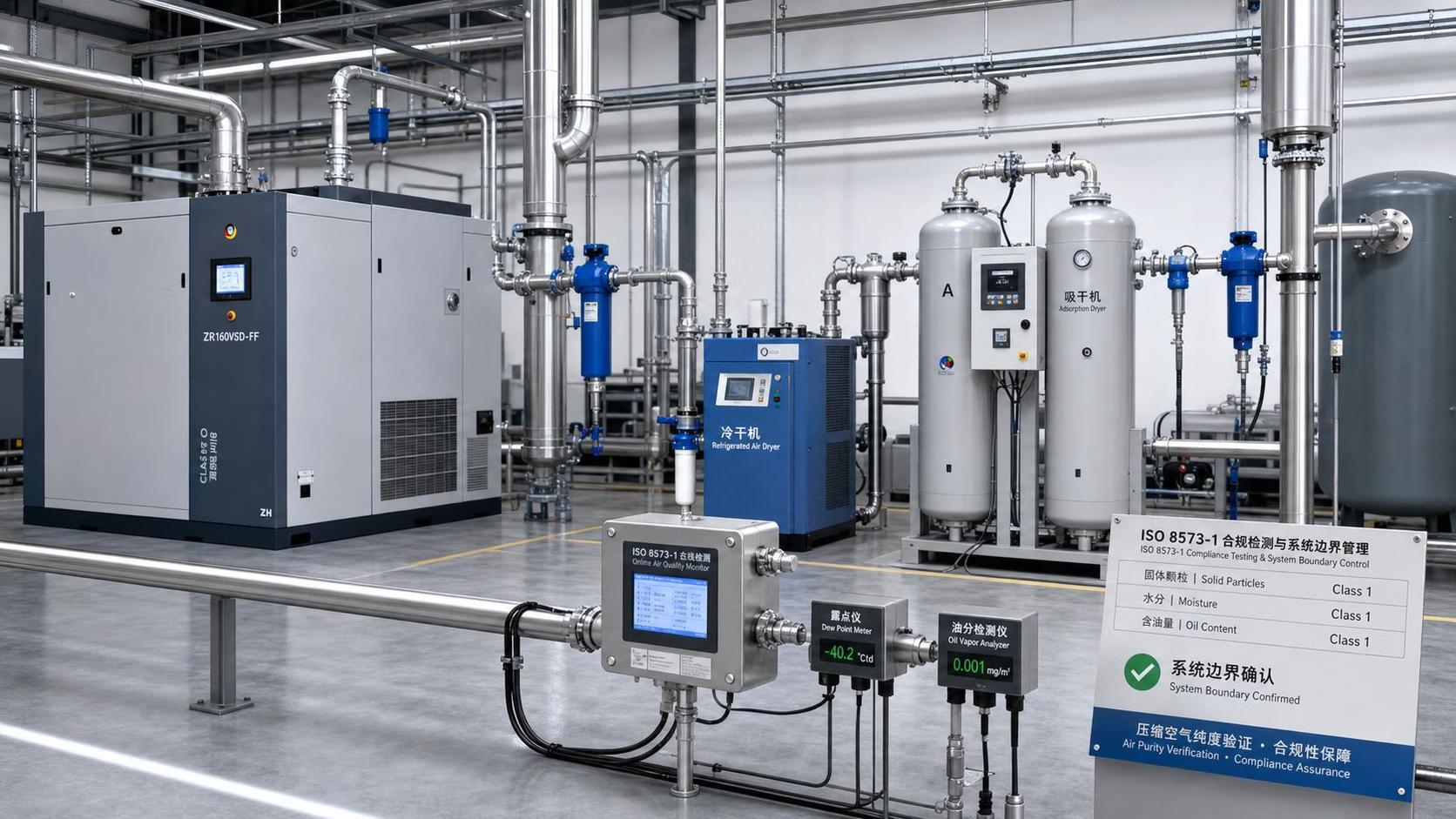
Specify the quality required at the point where air contacts the product, rather than relying only on the compressor’s construction. Define the contaminant to be measured, the sampling location, the operating condition, and the acceptance limit. If a compressed-air purity classification is used in a specification, state the required classes for particles, water, and total oil separately and confirm how compliance will be demonstrated. Total oil assessment needs to address vapor as well as liquid aerosol where vapor is relevant.
Sampling during an idle period can miss problems that occur when several presses start together or when air demand approaches the system’s operating capacity. Measurements should represent normal production and any known demanding conditions, such as changeovers or high-flow blow-off. At the same time, a single unfavorable result needs context: sampling equipment, hose condition, and the sampling procedure can affect the result.
Pressure readings also need context. Low pressure at a press can result from an undersized line, a restricted filter, excessive demand, or compressor capacity. Increasing system pressure without finding the restriction can increase air consumption and may place more stress on downstream components. A filter’s differential pressure is useful for identifying loading or restriction, but it is not proof that the outlet air meets an oil limit.
Trend results alongside production records. If a defect recurs at the same press while the main header tests clean, investigate the branch, local filter, hose, and nozzle. Conversely, similar contamination across several outlets points upstream toward shared treatment, storage, intake, or distribution. This distinction prevents repeated filter changes at the press from masking a common source.
Keep contamination from returning after maintenance
Maintenance creates opportunities for contamination to enter an otherwise controlled air path. A replacement hose stored on a dirty floor, sealant applied excessively inside a fitting, or a filter bowl reassembled with residue can introduce material downstream of the main treatment system. Keep components intended for clean-air service protected until installation, and follow equipment instructions for cleaning and reassembly.
Automatic condensate drains need attention because a blocked or failed drain can allow liquid to accumulate and move downstream. Filter elements and adsorption media also have finite service lives; replacement intervals should reflect the manufacturer’s guidance, operating conditions, and monitoring results. An element that looks clean may still have lost its ability to control vapor.
After work on a critical branch, return the line to service through a defined release procedure. This can include flushing into a safe collection point, inspecting the outlet, and testing when the change could affect product quality. Directing the first burst of air onto saleable material is a poor way to establish that the line is clean.
When a defect investigation confirms contamination, preserve the connection between the air finding and the affected production window. Record which outlets were involved, when the system was restored, and what evidence supports release. That record makes it easier to contain suspect material and to distinguish a corrected air-system fault from a recurring substrate or press problem.
Ready when you are. Send us a message to get started.
Related News
- How oil-free compressed air helps prevent printing defectsAuthor :Pneumatic Power Engineer

- Can oil-free vacuum pumps handle semiconductor etching gases?Author :Pneumatic Power Engineer

- AIRERA Showcases TUV Class 0-Certified Oil-Free Screw Compressor at COMVACAuthor :Pneumatic Power Engineer

- How to verify food-grade purity in compressed air systemsAuthor :Pneumatic Power Engineer

- What determines the price of pure air compression systems?Author :Pneumatic Power Engineer

- How to size oil-free compressors for instrumentation air demandAuthor :Pneumatic Power Engineer

- How Class 0 oil-free compressors protect product quality in food productionAuthor :Pneumatic Power Engineer

- How to verify compressed air cleanroom standards before installationAuthor :Pneumatic Power Engineer

- When oil free vacuum pumps make sense for European cleanroom projectsAuthor :Pneumatic Power Engineer

- When do pure air compression systems need ISO 8573-1 Class 0?Author :Pneumatic Power Engineer

- How do compressed air systems for electronics prevent contamination?Author :Pneumatic Power Engineer

- When does an oil-free process vacuum pump justify its higher cost?Author :Pneumatic Power Engineer

- Does ISO 9001 certification apply to compressed air quality?Author :Pneumatic Power Engineer

- How to Specify Clean Compressed Air Systems in Southeast Asia for Food and Pharma PlantsAuthor :Pneumatic Power Engineer

- How to Compare Oil Free Vacuum Pumps for Clean Process RequirementsAuthor :Pneumatic Power Engineer

- How to Evaluate a Clean Compressed Air Systems Supplier for ISO 8573-1 ComplianceAuthor :Pneumatic Power Engineer

- How to Choose the Right Oil-Free Vacuum PumpAuthor :Pneumatic Power Engineer

- VDI 2083 Update Makes Class 0 Proof MandatoryAuthor :Pneumatic Power Engineer

- When to Use Oil Free Vacuum Pumps for High Purity LinesAuthor :Pneumatic Power Engineer

- Compressed Air Solutions: When Oil-Free Systems Lower Total Operating CostAuthor :Pneumatic Power Engineer

- ATMOsphere Europe 2026 Adds Oil-free Systems ZoneAuthor :Pneumatic Power Engineer

- Oil-Free Compressors: Key Selection Criteria for Clean Air SystemsAuthor :Pneumatic Power Engineer

- How to Compare Oil Free Centrifugal Compressors for Stable Plant Air SupplyAuthor :Pneumatic Power Engineer

- Compressed Air Class 0 vs Oil-Free: What Really MattersAuthor :Pneumatic Power Engineer

- Oil-Free Compression Class 0: What the Standard Really Means in ProductionAuthor :Pneumatic Power Engineer

- Air Compression Cost Comparison: Oil-Free vs Screw Systems in Daily OperationAuthor :Pneumatic Power Engineer

- Saudi SASO Tightens IEC 63349-2 for Oil-Free CompressorsAuthor :Pneumatic Power Engineer

- Saudi SASO Tightens Oil-Free Compressor Efficiency RulesAuthor :Pneumatic Power Engineer

- Pure Air Compression Systems for Clean Production LinesAuthor :Pneumatic Power Engineer

- IEC 63349-2:2026 makes energy certification mandatoryAuthor :Pneumatic Power Engineer

- IEC 63349-2:2026 Sets New Entry Rules for Oil-Free Screw CompressorsAuthor :Pneumatic Power Engineer

- IEC 63349-2:2026 Takes Effect for Oil-Free Screw CompressorsAuthor :Pneumatic Power Engineer

- IEC 63349-2:2026 Sets New Efficiency Gate for Oil-Free Screw CompressorsAuthor :Pneumatic Power Engineer

- IEC 63349-2:2026 Takes Effect for Oil-Free Screw CompressorsAuthor :Pneumatic Power Engineer

- SABIC Methanol Force Majeure Extended, Tightening R134a/R407C FeedstocksAuthor :Pneumatic Power Engineer

- How to Evaluate Pneumatic Power Systems for Stable OutputAuthor :Pneumatic Power Engineer