


Can oil-free vacuum pumps handle semiconductor etching gases?




Can oil-free vacuum pumps handle semiconductor etching gases?
Yes—but only when the pump is engineered for the specific chemistry and operating conditions. Selecting oil-free vacuum pumps for semiconductor etching requires more than checking ultimate pressure. Corrosive gases, reactive byproducts, and particle buildup can compromise reliability even when a pump initially meets the chamber’s vacuum requirements.
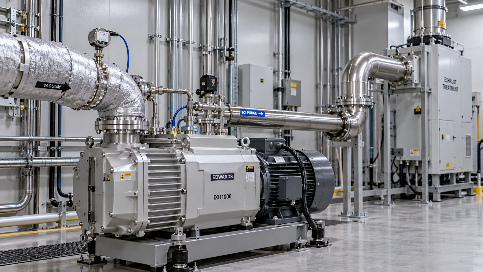
The distinction is between a pump that is merely oil-free and a dry vacuum system qualified for the process. Materials compatibility, internal temperature control, inert-gas purging, exhaust treatment, and shutdown behavior all affect suitability. A general-purpose dry pump should not be assumed suitable simply because its pumping chamber contains no oil.
“Oil-free” describes lubrication—not chemical resistance
In a dry vacuum pump, the swept gas path operates without oil serving as the pumping fluid or chamber lubricant. Bearings and gearboxes may still contain lubricants, isolated from the process stream by the pump’s sealing arrangement. Removing oil from the pumping chamber avoids oil-related contamination and degradation mechanisms, but it does not make exposed metals, coatings, or seals universally resistant to etch exhaust.
Semiconductor etching also exposes the pump to more than the gases listed in a recipe. Plasma reactions generate fragments and reaction products; wafer materials, masks, chamber deposits, and cleaning steps contribute additional species. Conditions change again as this mixture travels through the foreline and is compressed inside the pump.
The qualification question is therefore not “Can it pump chlorine?” but “Can this configuration handle the expected exhaust mixture throughout the complete operating cycle?” That cycle includes production, chamber cleaning, idle periods, controlled shutdown, and recovery after a utility interruption.
Start with the exhaust chemistry, not the pump catalog
Gas names alone are a weak basis for selection. Concentration, moisture, pressure, temperature, and exposure duration can change the failure mechanism. A supplier needs the recipe envelope and anticipated reaction products—not just the nominal process-gas list.
For example, silicon-containing exhaust species such as silicon tetrafluoride can react with moisture, producing corrosive species and solid reaction products. This makes air ingress and maintenance exposure relevant to reliability—not merely housekeeping concerns. The exact behavior still depends on the mixture and operating conditions.
Do not assume that installing a trap resolves every deposition problem. A collection device introduces conductance loss and becomes another location where reactive material accumulates. Its temperature, capacity, isolation arrangements, and cleaning procedure need their own review.
Pump architecture matters, but configuration decides suitability
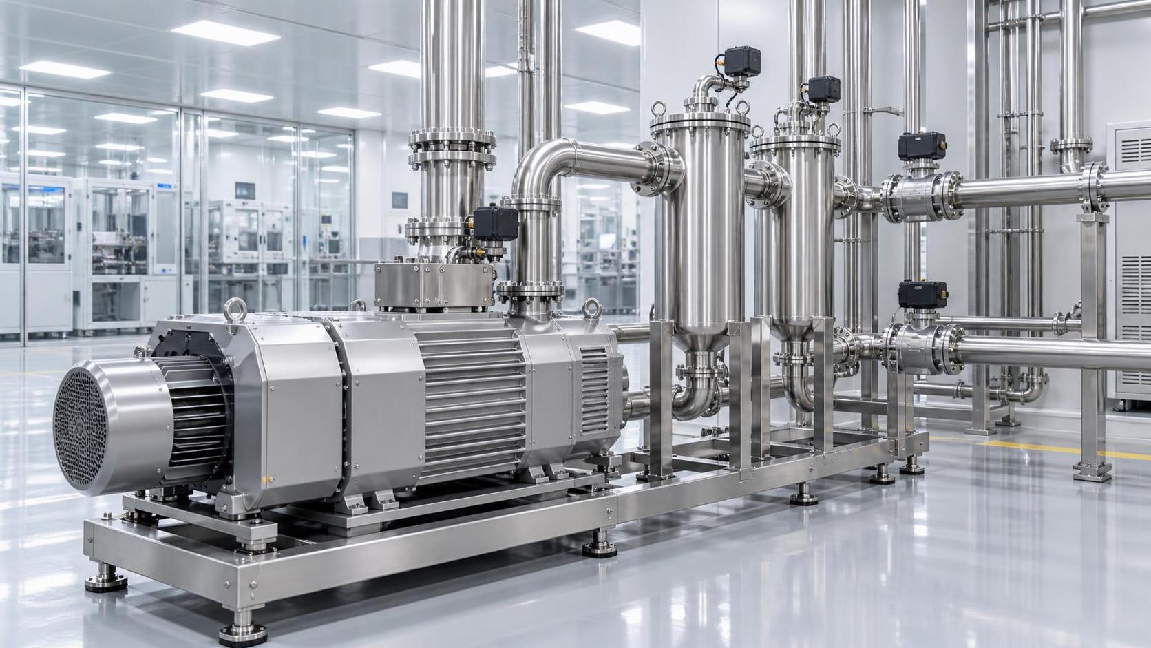
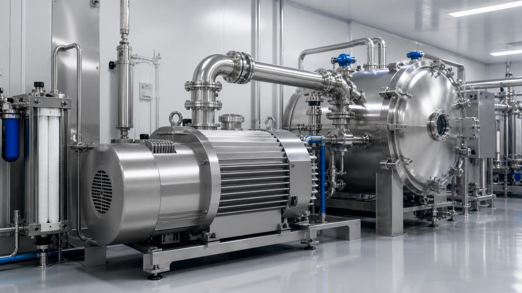
Dry screw and multistage Roots-type designs are established options in semiconductor vacuum systems. Either may be appropriate when configured for the application. Neither architecture, by itself, proves compatibility with a particular etch process.
Compare gas-path geometry, stage temperatures, clearances, sealing arrangements, and provisions for managing deposits. Ask which surfaces contact the process stream and whether the proposed chemical-duty configuration differs from the standard model. A coating is useful only within its qualified exposure conditions; it is not a substitute for reviewing the underlying materials and seals.
Where a turbomolecular pump serves the chamber, the dry backing pump must also keep foreline pressure within the turbopump’s permitted operating envelope during gas-flow peaks. A high nominal pumping speed does not guarantee this. Foreline conductance, booster configuration, purge additions, and exhaust restrictions affect the installed result.
Evaluate performance at the operating pressure
Ultimate pressure usually describes performance under low gas load. Etching is a flowing-gas application. More useful information includes pumping-speed curves across the relevant pressure range, allowable continuous throughput, transient response, and maximum permitted exhaust backpressure. Establish the test gas and conditions behind each curve, particularly when comparing suppliers.
An oversized pump can consume more utilities without improving chamber control if the limiting factor is a narrow foreline or throttle-valve arrangement. Size the system around the required pressure-flow envelope, with justified operating margin.
Control temperature across the entire exhaust path
Temperature management is often where an apparently suitable selection becomes unreliable. Cooling a gas stream can encourage condensation or deposition; excessive temperature can damage seals, exceed coating limits, or promote unwanted reactions. “Run it hotter” is not a complete engineering answer.
The objective is a chemistry-specific operating window from the chamber outlet through the foreline, pump stages, and exhaust connection. Compression changes local pressure and gas temperature, so a condition acceptable at the inlet may not remain acceptable deeper inside the pump.
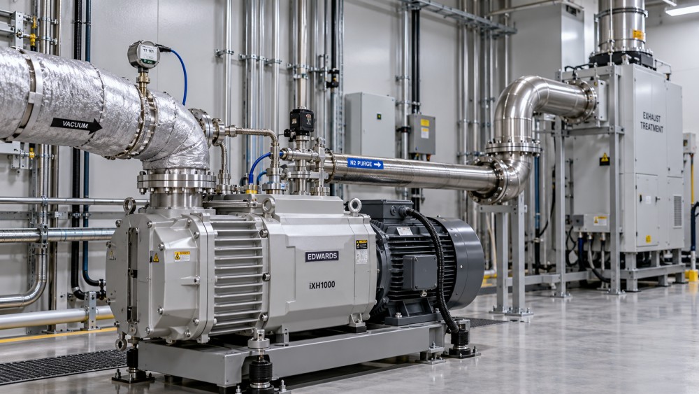
A useful system drawing should identify heated sections, temperature sensors, purge injection points, cooling connections, and the abatement interface. Look especially for unheated valves, flexible connectors, and transitions that could become deposition sites. Also check whether measured casing temperatures adequately represent the process-sensitive locations.
Warm-up and shutdown sequences deserve explicit acceptance criteria. Introducing process gas before temperatures stabilize, or allowing loaded equipment to cool without the specified purge, can undermine an otherwise sound design. These sequences should follow the qualified operating procedure rather than an assumed universal rule.
Purging and abatement are part of the selection
Nitrogen purging can protect seals, dilute process gases, and help manage deposition in designated areas. However, seal purge, internal process purge, and exhaust dilution serve different purposes. Their injection locations and required flows should be documented separately.
More purge is not automatically safer or better. Added gas increases the load on downstream piping and treatment equipment, and its effect on pumping performance depends on where it enters. Dilution also does not establish safety without considering the actual chemistry, mixing conditions, and credible fault scenarios.
The pump transports hazardous material; it does not necessarily render it harmless. Exhaust abatement must be matched to the expected compounds, total flow, and process variability. Treatment performance cannot be inferred from the pump specification.
Review the interface in both directions. An abatement fault or exhaust restriction can raise pump discharge pressure. A purge change can alter treatment loading. The equipment teams need agreed alarm thresholds, interlocks, and responses to loss of nitrogen, cooling, heating, extraction, or power. Continued operation after any such fault requires specific justification.
What to ask for before approving a shortlist
Give each supplier the same process envelope and request a written application assessment. A generic statement that a model is “semiconductor compatible” leaves too much unresolved.
- Process boundaries: Gas mixtures, expected byproducts, flow peaks, pressure range, recipe sequence, cleaning steps, and anticipated particle loading.
- Configuration boundaries: Exact pump variant, exposed materials, coating limitations, purge requirements, temperature settings, and permitted backpressure.
- Qualification basis: Relevant application experience or test results, including how those conditions differ from the proposed duty.
- Maintenance provisions: Deposit inspection, isolation and decontamination procedures, service access, spare-pump arrangements, and hazardous-residue handling.
- Acceptance plan: Measurements, alarm checks, process-stability criteria, and responsibility for resolving pump–foreline–abatement interface problems.
A pilot assessment should reproduce representative recipe transitions and cleaning cycles, not just demonstrate stable pressure on an inert gas. Useful indicators include inlet pressure, drive current, temperatures, purge delivery, and exhaust backpressure. Trends can reveal accumulating restriction before a hard fault occurs, although no single signal diagnoses every failure mode.
Treat proposed maintenance intervals as application-dependent until supported by relevant evidence. A clean-gas endurance result cannot establish service life under corrosive, deposit-forming exhaust.
Compare operating burden, not just purchase price
The economic comparison should include electricity, nitrogen, cooling, heaters, abatement loading, maintenance labor, and downtime exposure. Compare these at equivalent process duty and protection settings. Low power consumption achieved by reducing a required purge or thermal safeguard is not a valid efficiency improvement.
This system-level view aligns with GTC-Matrix’s coverage of vacuum processes, industrial cooling, compression, and energy conversion. Pump efficiency cannot be separated from the thermal and utility systems that keep it reliable. A modest component-level saving may disappear if it increases nitrogen demand, treatment load, or service frequency elsewhere.
Oil-free vacuum pumps can handle semiconductor etching gases when the chemistry, configuration, and operating envelope are matched. Before approval, establish three things in writing: what the pump can tolerate, which protective conditions must remain available, and how suitability will be verified under representative process duty. If those answers remain vague, the selection is not yet complete.
Ready when you are. Send us a message to get started.
Related News
- Can oil-free vacuum pumps handle semiconductor etching gases?Author :Pneumatic Power Engineer

- AIRERA Showcases TUV Class 0-Certified Oil-Free Screw Compressor at COMVACAuthor :Pneumatic Power Engineer

- How to verify food-grade purity in compressed air systemsAuthor :Pneumatic Power Engineer

- What determines the price of pure air compression systems?Author :Pneumatic Power Engineer

- How to size oil-free compressors for instrumentation air demandAuthor :Pneumatic Power Engineer

- How Class 0 oil-free compressors protect product quality in food productionAuthor :Pneumatic Power Engineer

- How to verify compressed air cleanroom standards before installationAuthor :Pneumatic Power Engineer

- When oil free vacuum pumps make sense for European cleanroom projectsAuthor :Pneumatic Power Engineer

- When do pure air compression systems need ISO 8573-1 Class 0?Author :Pneumatic Power Engineer

- How do compressed air systems for electronics prevent contamination?Author :Pneumatic Power Engineer

- When does an oil-free process vacuum pump justify its higher cost?Author :Pneumatic Power Engineer

- Does ISO 9001 certification apply to compressed air quality?Author :Pneumatic Power Engineer

- How to Specify Clean Compressed Air Systems in Southeast Asia for Food and Pharma PlantsAuthor :Pneumatic Power Engineer

- How to Compare Oil Free Vacuum Pumps for Clean Process RequirementsAuthor :Pneumatic Power Engineer

- How to Evaluate a Clean Compressed Air Systems Supplier for ISO 8573-1 ComplianceAuthor :Pneumatic Power Engineer

- How to Choose the Right Oil-Free Vacuum PumpAuthor :Pneumatic Power Engineer

- VDI 2083 Update Makes Class 0 Proof MandatoryAuthor :Pneumatic Power Engineer

- When to Use Oil Free Vacuum Pumps for High Purity LinesAuthor :Pneumatic Power Engineer

- Compressed Air Solutions: When Oil-Free Systems Lower Total Operating CostAuthor :Pneumatic Power Engineer

- ATMOsphere Europe 2026 Adds Oil-free Systems ZoneAuthor :Pneumatic Power Engineer

- Oil-Free Compressors: Key Selection Criteria for Clean Air SystemsAuthor :Pneumatic Power Engineer

- How to Compare Oil Free Centrifugal Compressors for Stable Plant Air SupplyAuthor :Pneumatic Power Engineer

- Compressed Air Class 0 vs Oil-Free: What Really MattersAuthor :Pneumatic Power Engineer

- Oil-Free Compression Class 0: What the Standard Really Means in ProductionAuthor :Pneumatic Power Engineer

- Air Compression Cost Comparison: Oil-Free vs Screw Systems in Daily OperationAuthor :Pneumatic Power Engineer

- Saudi SASO Tightens IEC 63349-2 for Oil-Free CompressorsAuthor :Pneumatic Power Engineer

- Saudi SASO Tightens Oil-Free Compressor Efficiency RulesAuthor :Pneumatic Power Engineer

- Pure Air Compression Systems for Clean Production LinesAuthor :Pneumatic Power Engineer

- IEC 63349-2:2026 makes energy certification mandatoryAuthor :Pneumatic Power Engineer

- IEC 63349-2:2026 Sets New Entry Rules for Oil-Free Screw CompressorsAuthor :Pneumatic Power Engineer

- IEC 63349-2:2026 Takes Effect for Oil-Free Screw CompressorsAuthor :Pneumatic Power Engineer

- IEC 63349-2:2026 Sets New Efficiency Gate for Oil-Free Screw CompressorsAuthor :Pneumatic Power Engineer

- IEC 63349-2:2026 Takes Effect for Oil-Free Screw CompressorsAuthor :Pneumatic Power Engineer

- SABIC Methanol Force Majeure Extended, Tightening R134a/R407C FeedstocksAuthor :Pneumatic Power Engineer

- How to Evaluate Pneumatic Power Systems for Stable OutputAuthor :Pneumatic Power Engineer

- Oil-Free Compression vs Lubricated Systems: Key Trade-OffsAuthor :Pneumatic Power Engineer
![]()