



When does gasketed plate heat exchanger technology suit your process?




A gasketed plate heat exchanger is usually the right choice when a process needs high thermal efficiency, close temperature approach, accessible cleaning, or future capacity adjustment without replacing the entire unit. It is especially attractive where utilities are expensive, space is limited, and the process fluids can be handled safely with elastomer gaskets and suitable plate materials.
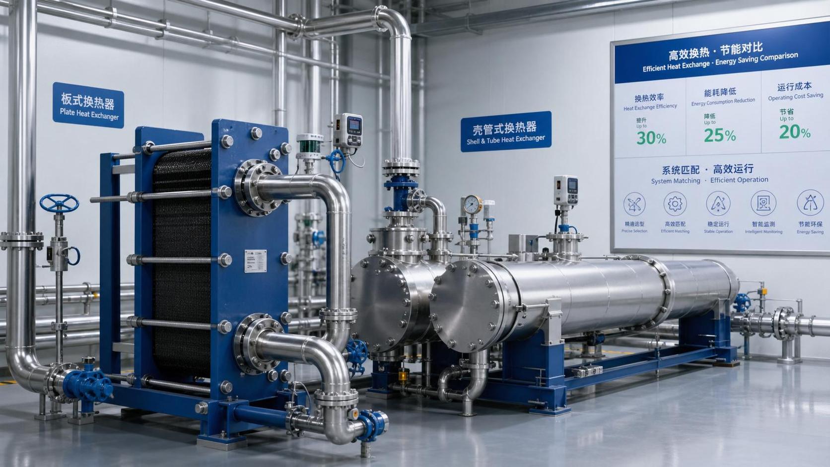
The decision becomes more important when an existing shell-and-tube exchanger cannot maintain outlet temperature, requires excessive utility flow, or is difficult to clean between production runs. In these situations, heat exchanger technology gasketed plate designs can reduce thermal resistance and simplify service access. They are not, however, the automatic answer for every duty. Very high pressures, severe thermal cycling, incompatible chemicals, particulate-heavy streams, or leakage-intolerant media may point toward another exchanger construction.
Start with the process problem, not the exchanger type
Selection often goes wrong because the discussion begins with available footprint or nominal heat duty alone. A more useful starting point is the operating problem that the exchanger must solve. Is the process struggling to cool a viscous liquid? Is recovered heat being wasted because the required temperature approach is too close for the existing unit? Is cleaning downtime disrupting a batch schedule? Each problem directs attention to a different part of the gasketed plate exchanger design.
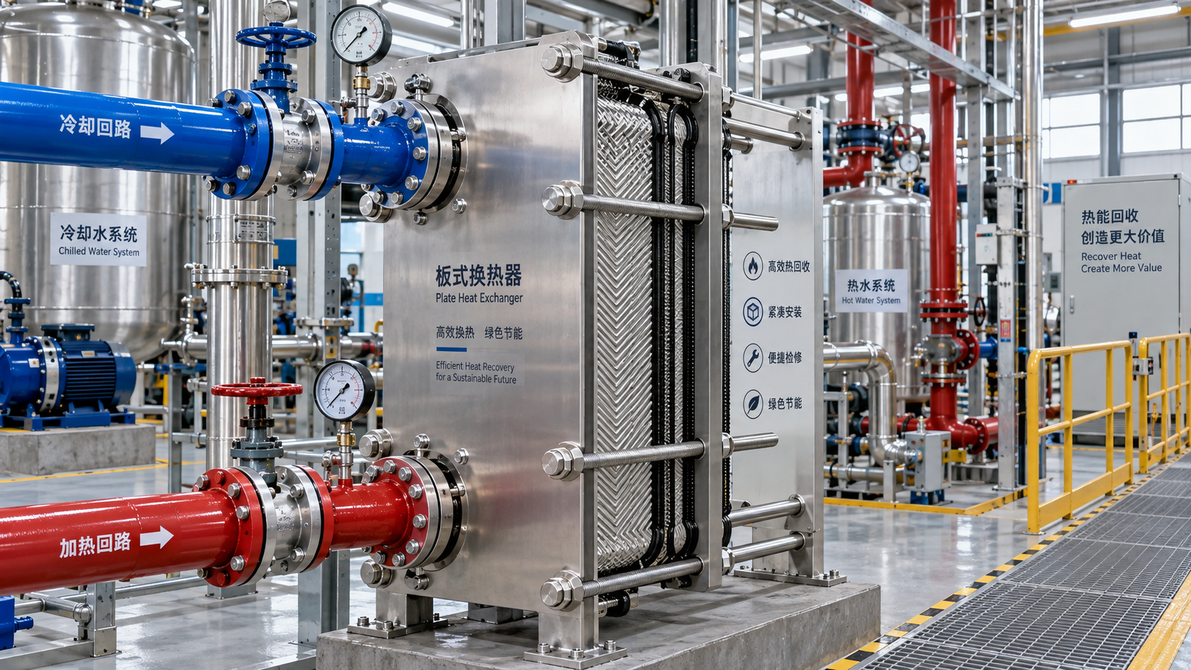
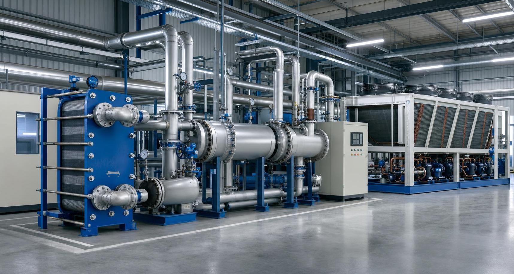
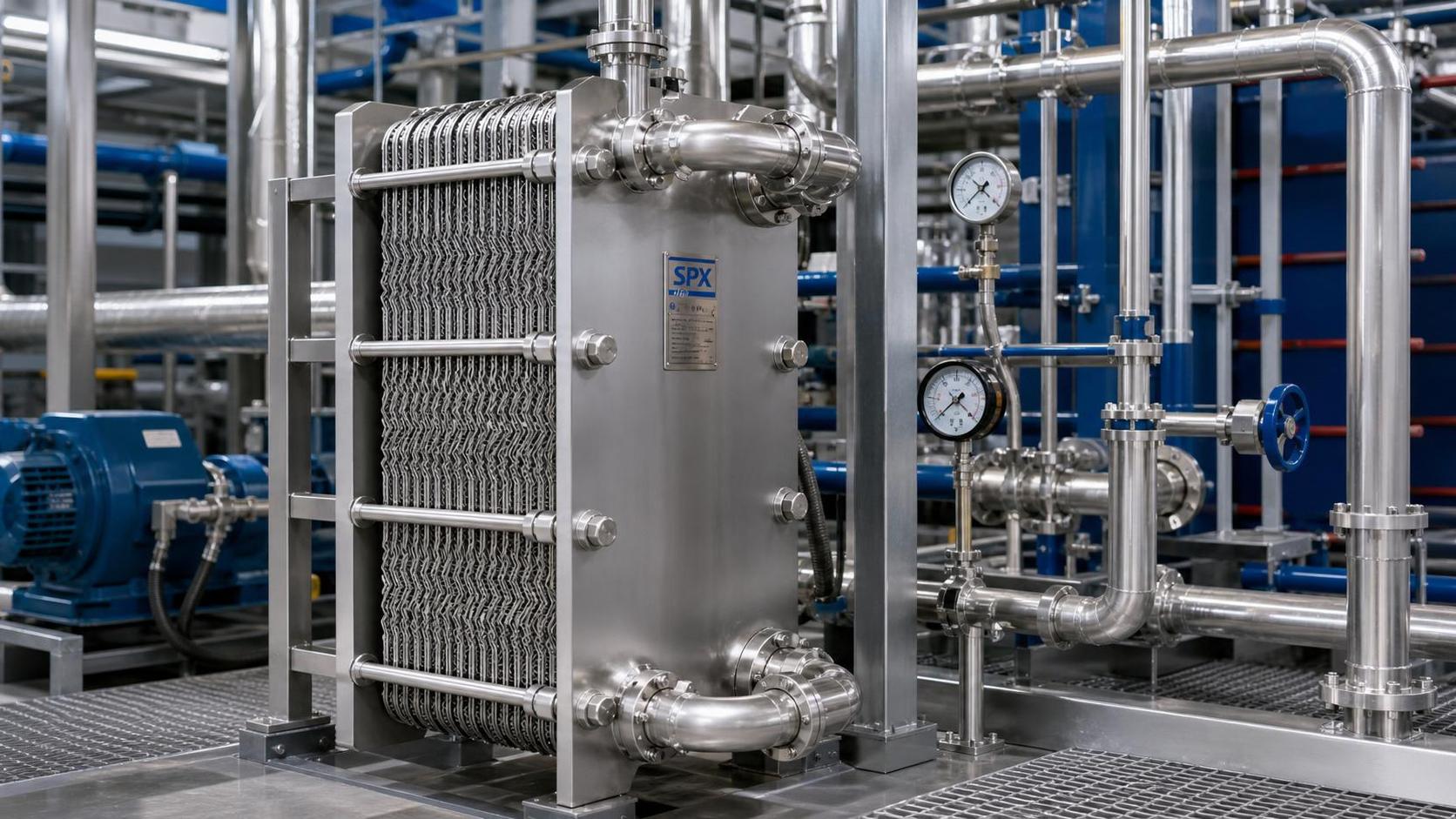
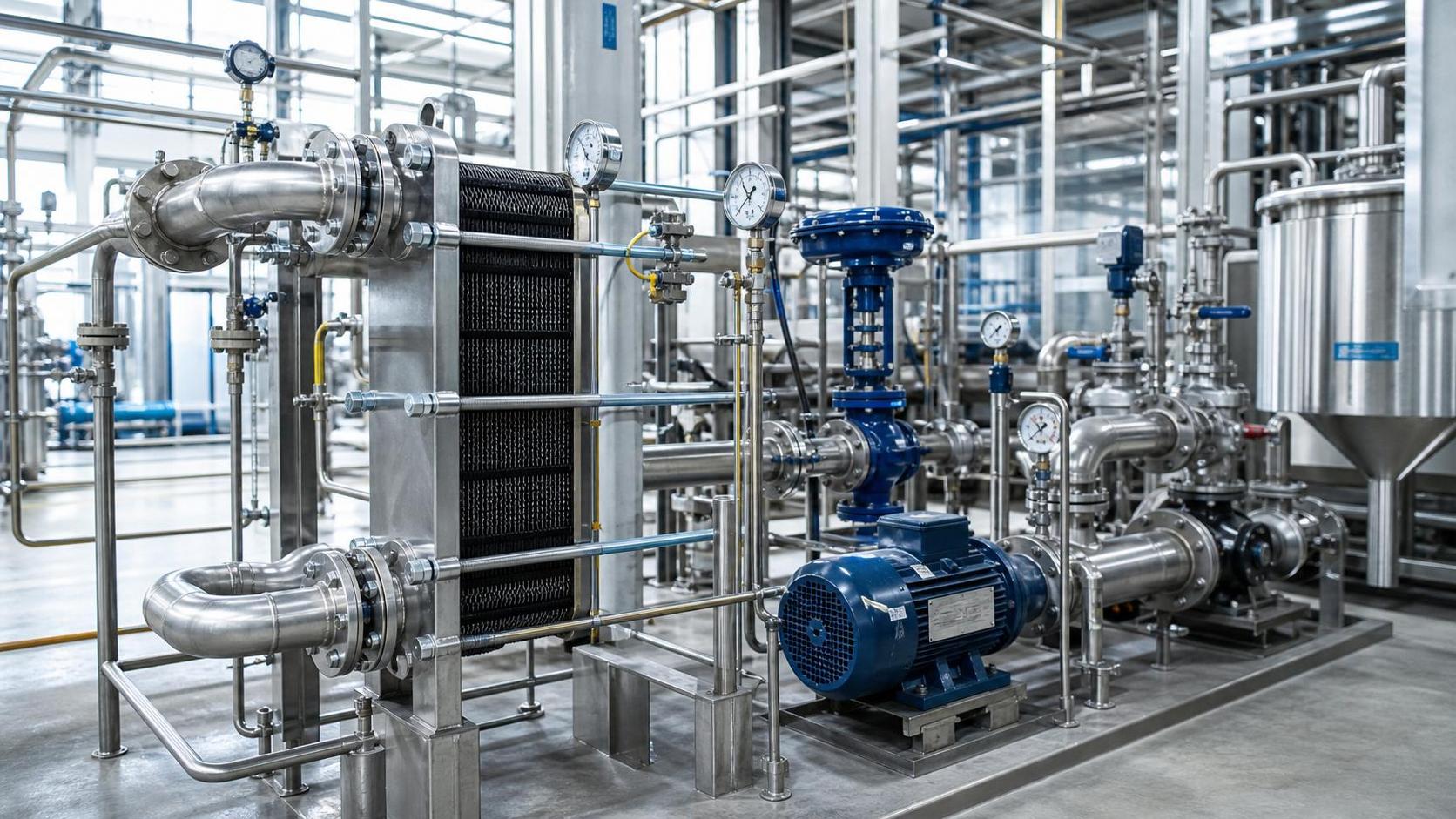
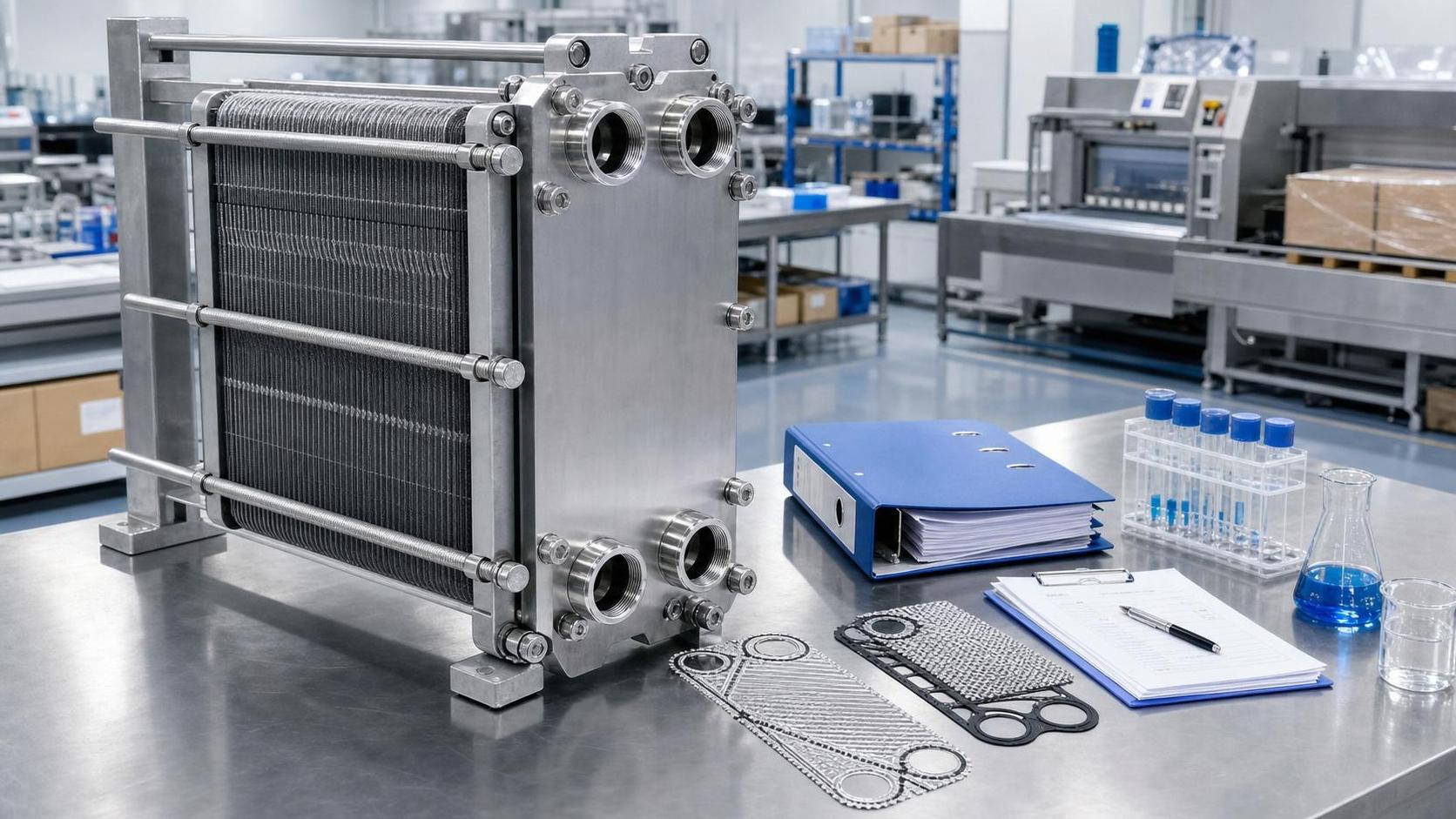
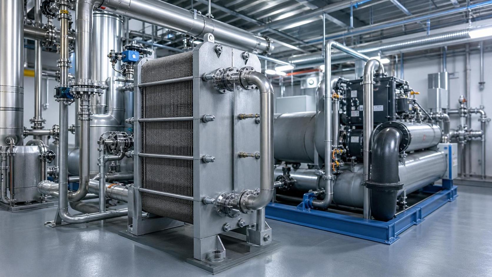
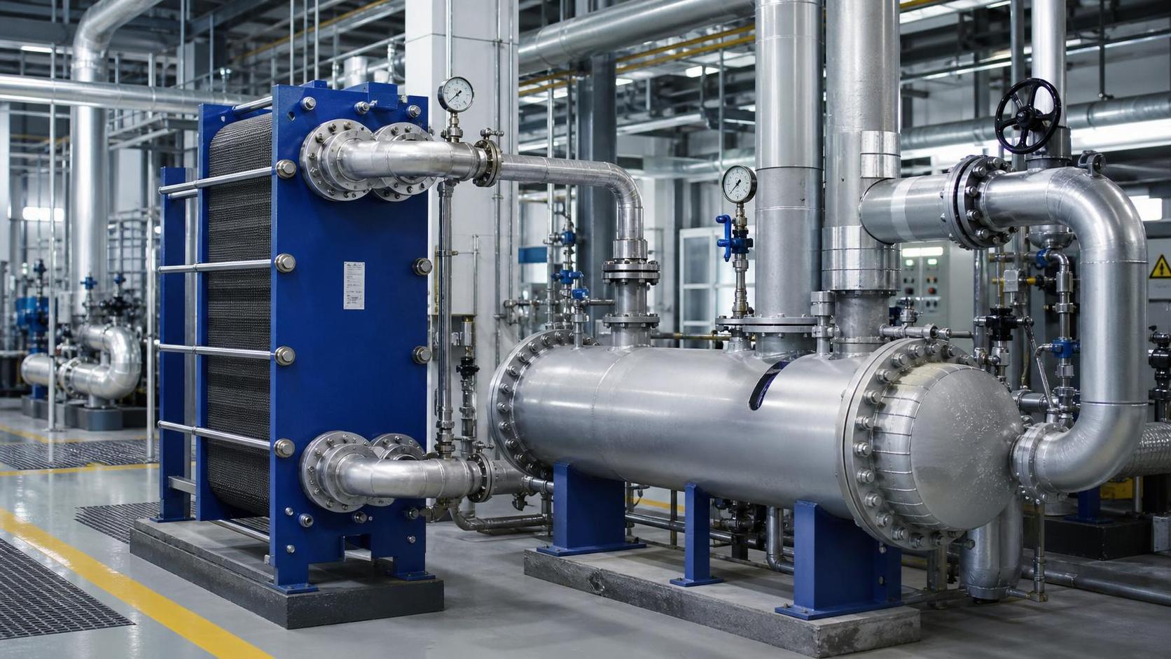
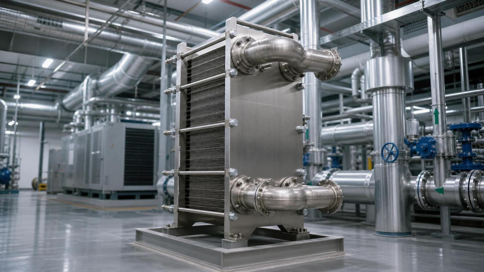
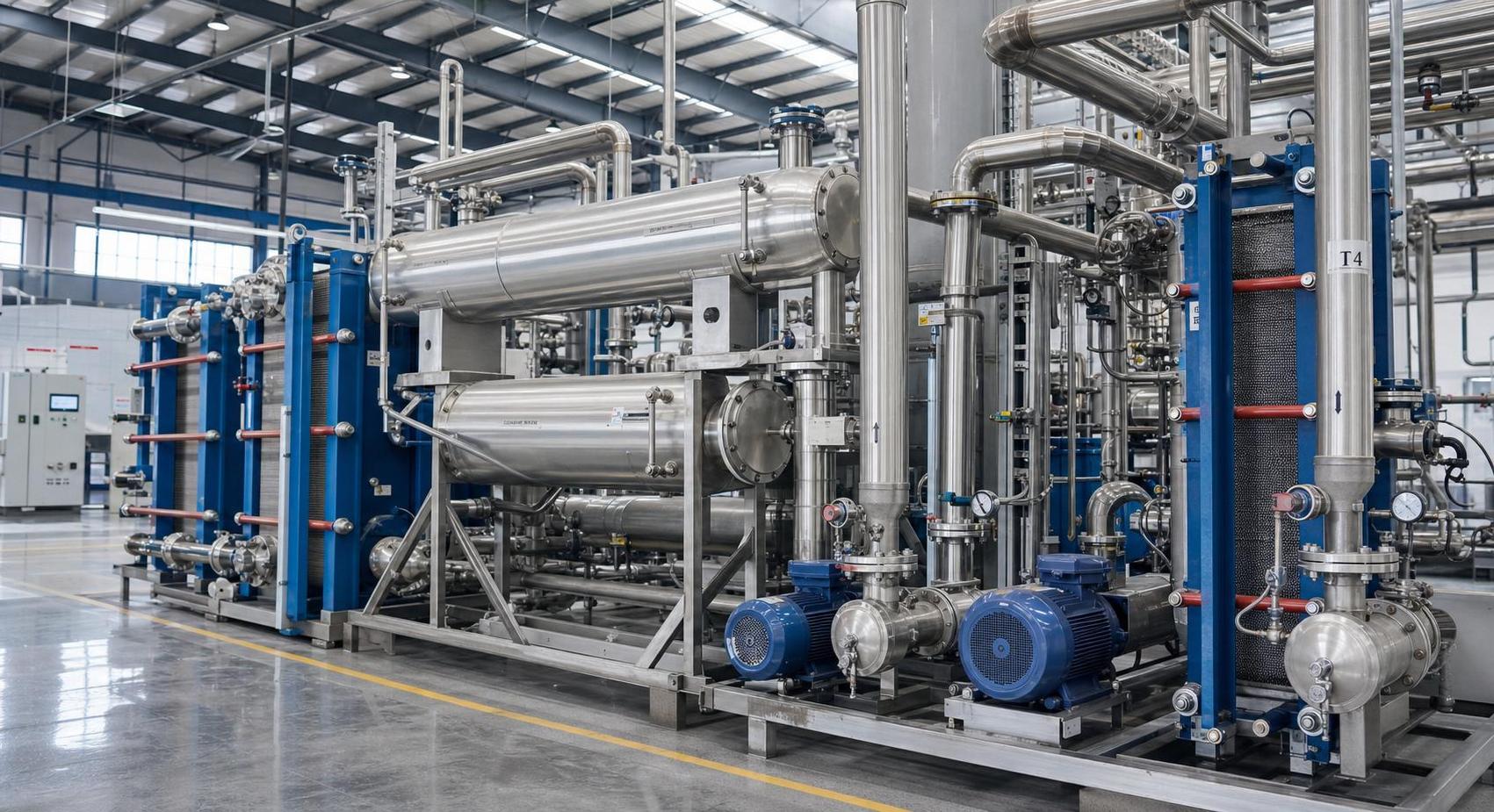
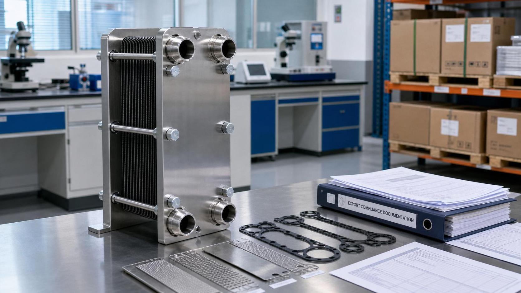
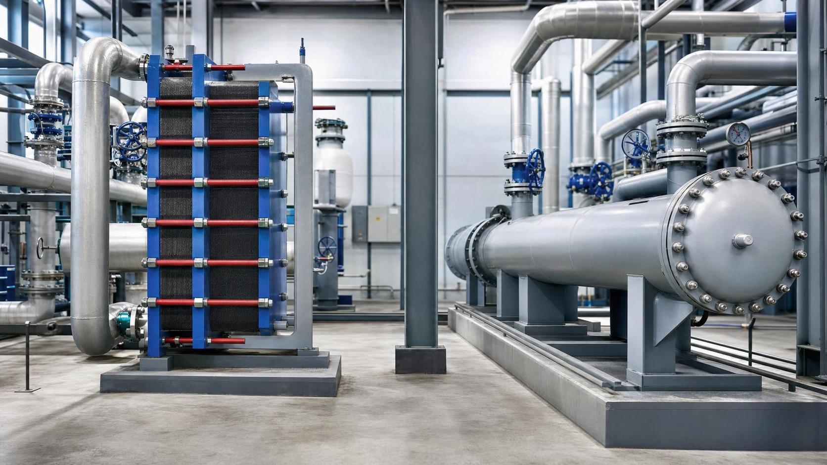
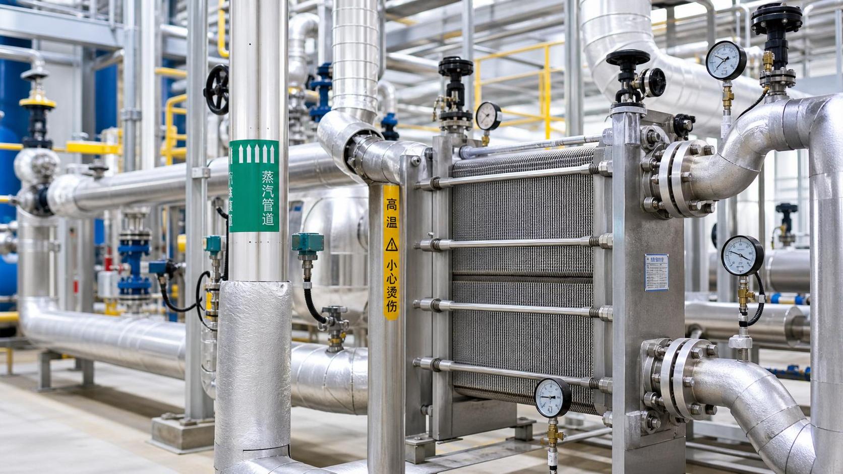
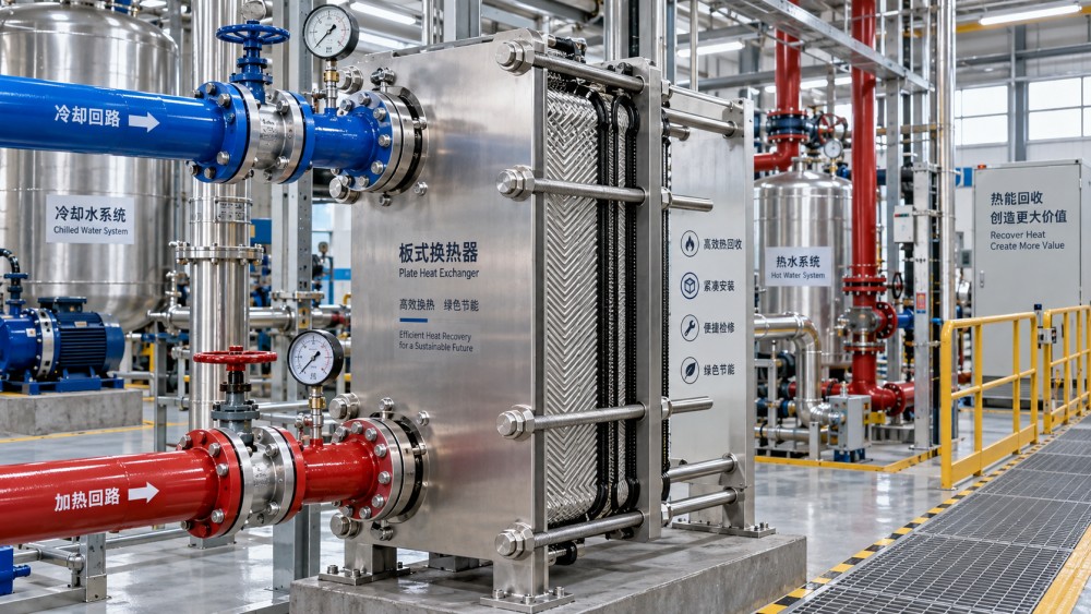
A gasketed plate unit consists of corrugated metal plates compressed in a frame. Gaskets route the hot and cold streams through alternating channels. The plate corrugation promotes turbulence, which improves heat transfer and limits the thickness of the boundary layer next to the plate surface. Because the flow arrangement is commonly close to true counter-current operation, the exchanger can often achieve a tighter temperature approach than conventional designs at comparable duties.
That combination suits processes where the temperature difference is limited but heat still needs to move efficiently. Heat recovery between two liquid streams is a typical example: a warm process stream may preheat incoming water, feedstock, or cleaning fluid before it reaches a heater. The value is not simply in transferring heat; it is in doing so without requiring a large driving temperature difference.
Conditions that strongly favor a gasketed plate arrangement
The technology generally fits best when both sides are liquids or liquid-like streams with reasonably predictable flow rates. Water, glycol mixtures, clean process liquids, aqueous solutions, and many food, chemical, and utility duties are common candidates, subject to material compatibility. The following conditions usually strengthen the case.
- A close outlet-temperature approach is needed. Counter-current plate channels can support tight approaches when the thermal design, fouling allowance, and flow control are appropriate.
- Utility consumption matters. Better heat recovery or a lower required utility temperature can improve the energy balance of heating and cooling loops.
- Space is restricted. Plate packs can provide substantial surface area within a compact frame compared with many tubular arrangements.
- The duty may grow or change. Additional plates can often be installed within the available frame capacity, provided the connections, pressure drop, tie bolts, and frame dimensions allow it.
- Mechanical cleaning is expected. Opening the frame gives direct access to individual plate surfaces, allowing inspection and cleaning rather than relying only on chemical circulation.
- Fast thermal response is useful. The low internal liquid volume can help systems respond more quickly to changes in flow or temperature.
These benefits are connected. A compact exchanger is not automatically efficient, and a close temperature approach is not automatically economical. The selection is sound when the temperature program, allowable pressure drop, cleaning method, and material limits all support the same configuration.
Read the temperature program before comparing equipment
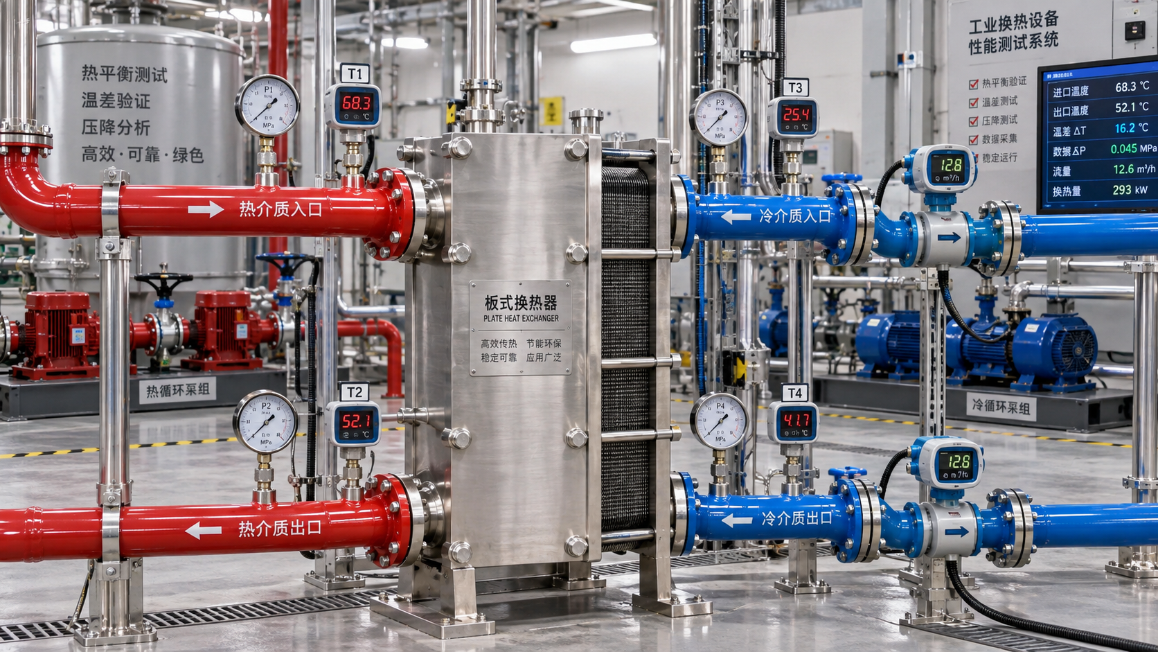
The first calculation should establish the hot-side and cold-side inlet and outlet temperatures, expected flow ranges, specific heat where relevant, and required duty. From this information, evaluate the terminal temperature differences and the log mean temperature difference. The result shows whether the process has enough thermal driving force and whether counter-current flow offers a practical advantage.
A gasketed plate exchanger is particularly worth evaluating when the cold-side outlet must approach the hot-side outlet closely, or when heat recovery is limited by a small temperature difference. But a tight design margin also leaves less room for fouling, flow variation, sensor error, and control instability. A unit sized exactly at clean conditions may fail to meet outlet temperature after deposits build up or when production throughput changes.
Consider a cooling duty where chilled water must cool a process liquid to a temperature only slightly above the chilled-water inlet. Plate technology may make that duty feasible with a manageable surface area. Yet the design still needs to account for realistic fouling resistance and for the possibility that chilled-water temperature rises during peak demand. A clean thermal calculation alone is not a reliable selection basis.
Do not treat pressure drop as a secondary detail
The same corrugation that improves heat transfer also produces pressure drop. Higher channel velocity generally increases turbulence and thermal performance, but it may increase pumping energy, affect upstream control valves, or reduce flow through a shared utility circuit. A process line with little pressure margin may require a wider-gap plate pattern, a larger exchanger, parallel units, or a different exchanger type.
Ask for separate allowable pressure-drop limits for each side. The hot and cold circuits often have different constraints. A cooling-water loop may tolerate more pressure drop than a low-pressure process stream, while a viscous product stream may need larger channels even if the utility side can run at higher velocity.
Fluid behavior determines whether the channels will stay usable
Gasketed plate heat exchangers are highly effective with clean or moderately fouling liquids, but the plate channels are not a substitute for sensible upstream conditioning. Fibers, weld debris, scale flakes, crystals, sticky solids, or large suspended particles can obstruct narrow passages. The risk rises when velocity is low, when fluid temperature crosses a precipitation point, or when the stream contains material that changes viscosity sharply as it cools.
Before selecting a channel geometry, identify what the fluid can become during normal operation, startup, shutdown, and cleaning. A liquid that appears clean at reactor outlet may form solids after cooling. A wash stream may carry loosened deposits that are absent during steady production. A cooling-water circuit may introduce biological material or corrosion debris after maintenance. These details influence strainer placement, plate gap, flow distribution, and cleaning frequency.
Viscosity also deserves careful treatment. Plate exchangers can work with viscous fluids, but a high-viscosity stream loses pressure rapidly and may not develop sufficient turbulence in a standard narrow channel. Increasing plate count is not always the answer because it can reduce velocity further. Wider-gap plates, multiple passes arranged carefully, staged cooling, or a different exchanger design may provide a more stable result.
Gasket and plate materials are part of the process design
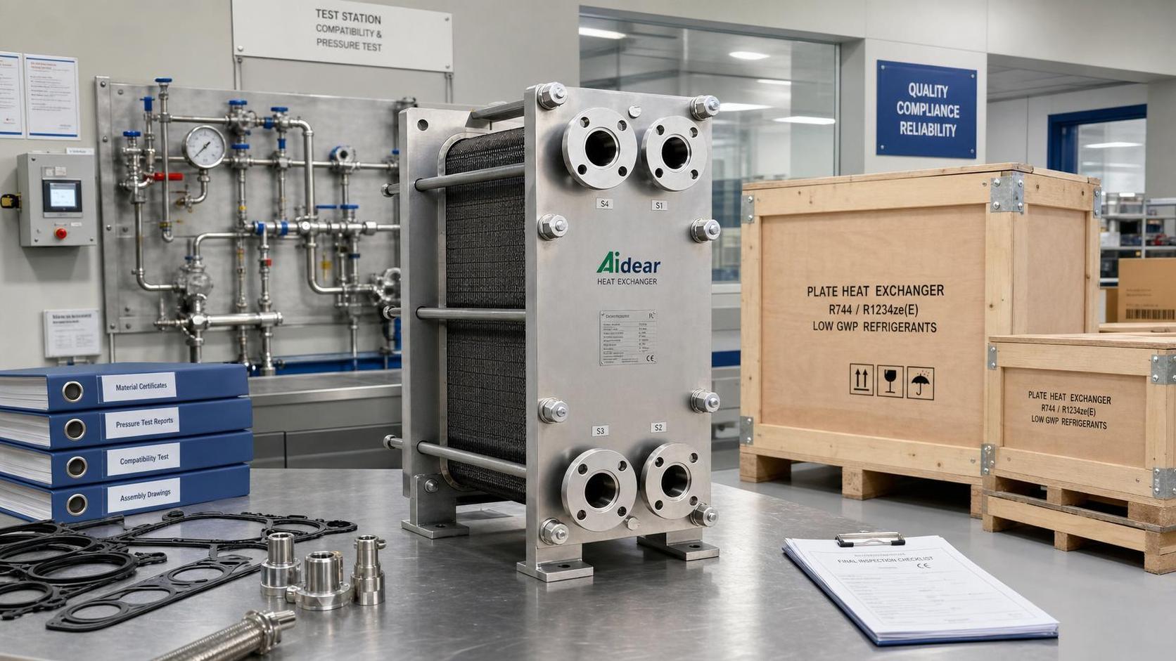
The term “gasketed” should trigger a compatibility review early in the evaluation. The gaskets seal and separate the channels, so their suitability depends on temperature, pressure, chemical exposure, cleaning agents, and operating cycles. A gasket that performs well with a neutral water loop may not tolerate oils, solvents, oxidizing cleaners, steam exposure, or repeated high-temperature excursions.
Plate material must also resist corrosion under the actual fluid chemistry, including concentration changes at heated surfaces and during cleaning. Chloride-bearing water, acidic solutions, alkaline cleaning chemicals, and trace contaminants can change the material decision. It is not enough to review normal operating fluid; examine startup fluid, cleaning-in-place chemistry, sanitizing chemicals, accidental contamination scenarios, and stagnant periods.
Temperature cycling matters because it loads the gasket and can influence long-term sealing performance. Frequent starts and stops, abrupt utility changes, or repeated exposure to temperatures near material limits should be stated in the specification. The same applies to vacuum conditions. If one side can be isolated and cool rapidly while the other side remains hot, the unit may see conditions that differ significantly from steady-state operation.
Where the technology becomes a poor fit
Gasketed plate exchangers should be treated cautiously when the consequences of external leakage are unacceptable or when the process medium is hazardous and the sealing arrangement does not provide sufficient risk control. Welded, semi-welded, double-wall, shell-and-tube, or other specialized constructions may be more appropriate depending on the duty.
They can also be unsuitable where operating pressure or temperature exceeds practical gasket and frame limits, where steam condensation creates difficult control or vibration conditions, or where severe fouling cannot be managed with channel selection and cleaning. Gas cooling, two-phase duties, and flashing services require specialized thermal and mechanical evaluation rather than assuming a liquid-service plate design will translate directly.
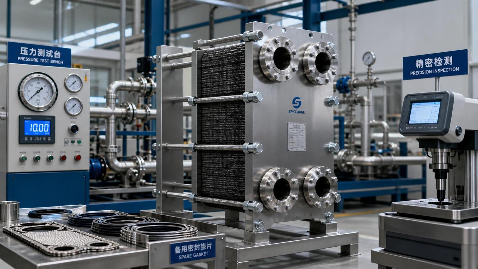
Another warning sign is a process that cannot be shut down or isolated for inspection. Although gasketed units are maintainable, maintenance still requires clearance, lifting access, controlled tightening, spare gaskets or plates when needed, and a safe method to handle residual process liquid. “Easy to clean” is only true when the installation makes opening and reassembly practical.
Evaluate maintainability at the same time as thermal performance
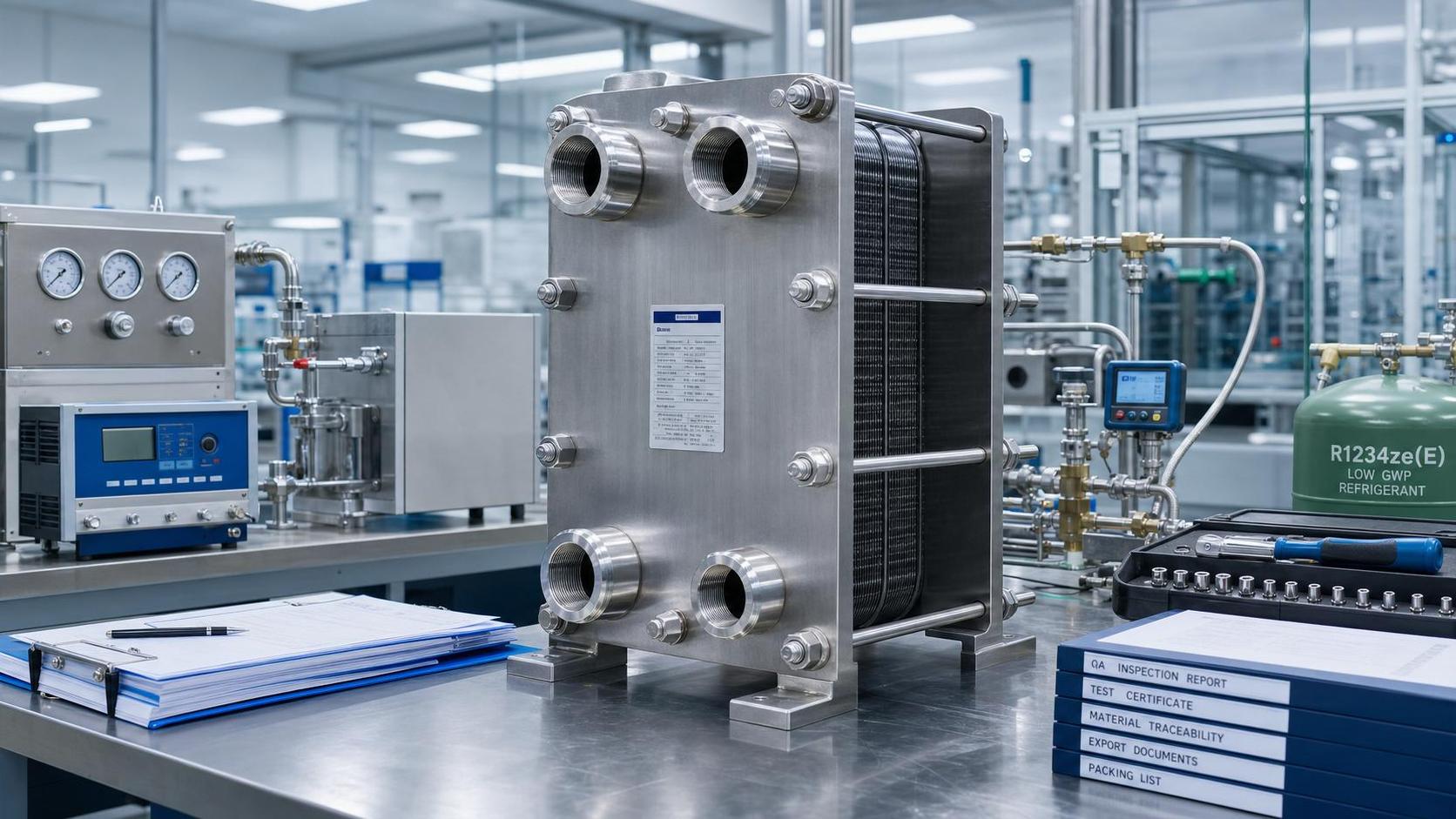
A reliable selection includes the maintenance environment, not only the exchanger datasheet. Confirm that there is enough floor space to pull the movable frame plate back and remove individual plates. Check the weight and handling requirements of the plate pack, isolation valve locations, drainability, venting, and whether nearby piping prevents frame opening.
Cleaning strategy should be matched to the expected deposit. Chemical cleaning may remove mineral scale or organic films without opening the unit, but it will not solve every blockage. Mechanical cleaning allows direct inspection but requires careful plate handling to avoid damage and correct gasket seating on reassembly. Monitoring differential pressure, outlet temperatures, and utility flow provides an earlier indication of fouling than waiting for a complete loss of thermal duty.
Specify a realistic fouling scenario rather than using a generic allowance without context. If deposits are likely, decide what event will trigger cleaning: rising pressure drop, inability to meet outlet temperature, reduced heat-recovery value, or a scheduled production interval. This links the exchanger design to an operational decision instead of leaving performance decline to be discovered after the process is already affected.
A practical selection sequence
- Define the normal, minimum, and maximum operating cases, including flows, temperatures, pressures, physical properties, and required duty.
- Set separate allowable pressure drops for both circuits and identify whether pump capacity can change later.
- Describe fluid cleanliness, particle characteristics, viscosity behavior, scaling tendency, and cleaning chemicals.
- Review plate and gasket compatibility against process, utility, cleaning, and upset conditions.
- Decide how close the outlet temperatures must be under fouled, not merely clean, conditions.
- Check installation clearance, isolation, drainage, lifting, and access for opening the frame.
- Compare the proposed plate pattern, pass arrangement, fouling allowance, and expansion capacity against the actual operating envelope.
A gasketed plate heat exchanger is most convincing when it solves a defined thermal limitation while remaining serviceable in the plant. Its strengths are high liquid-to-liquid heat transfer, compactness, accessible plates, and adjustment potential. Its limits are equally practical: channel blockage, pressure drop, gasket compatibility, operating extremes, and the realities of maintenance access. A selection based on all of those factors is far more dependable than choosing by compact size or headline heat duty alone.
Related News
- When does gasketed plate heat exchanger technology suit your process?Author :Thermodynamics Analyst

- When does heat recovery improve data center cooling efficiency?Author :Thermodynamics Analyst

- How Do I Verify Heat Transfer Calculations in a Supplier Quotation?Author :Thermodynamics Analyst

- How to evaluate a plate heat exchangers supplier before orderingAuthor :Thermodynamics Analyst

- EU Tightens Fatigue Checks for Plate Heat ExchangersAuthor :Thermodynamics Analyst

- EU PFAS Rule Adds New Export Filing for Cooling EquipmentAuthor :Thermodynamics Analyst

- EU EN 13445-4:2026 Adds Fatigue Report RequirementAuthor :Thermodynamics Analyst

- EU Updates EN 13445-4 for Plate ExchangersAuthor :Thermodynamics Analyst

- How to Compare Energy-Efficient Heat Exchange SolutionsAuthor :Thermodynamics Analyst

- Brazed Plate Exchanger Design: 7 Factors That Affect Heat TransferAuthor :Thermodynamics Analyst

- EU CBAM Pilot List Adds Plate ExchangersAuthor :Thermodynamics Analyst

- How Heat Exchange Systems Improve Temperature Control StabilityAuthor :Thermodynamics Analyst

- Japan to Require Efficiency Labels for Plate ExchangersAuthor :Thermodynamics Analyst

- EU REACH Adds PFAS Ban for Plate Heat ExchangersAuthor :Thermodynamics Analyst

- India Enforces BIS Rule for Plate Heat ExchangersAuthor :Thermodynamics Analyst

- DIN EN 13445-6:2026 Tightens Plate Exchanger CE RulesAuthor :Thermodynamics Analyst

- EU REACH Restricts PFAS Seals for Plate Heat ExchangersAuthor :Thermodynamics Analyst

- India Mandates BIS Certification for Imported Plate ExchangersAuthor :Thermodynamics Analyst

- Vietnam Requires QR Labels on Imported Plate Heat ExchangersAuthor :Thermodynamics Analyst

- EU EN 13445-4:2026 Tightens NDT Rules for Heat ExchangersAuthor :Thermodynamics Analyst

- EPA Clears R-1234ze(E) for Plate Exchanger SystemsAuthor :Thermodynamics Analyst
 for Plate Exchanger Systems")
- Heat Exchange Equipment Selection: Key Performance Checks Before You Compare ModelsAuthor :Thermodynamics Analyst

- ASHRAE 90.1-2026 Raises Plate Exchanger Efficiency ThresholdAuthor :Thermodynamics Analyst

- Heat Exchange Systems: How to Choose the Right SetupAuthor :Thermodynamics Analyst

- EPA SNAP 89 Takes Effect for Plate ExchangersAuthor :Thermodynamics Analyst

- How to Compare Heat Exchange Solutions for Lower Energy UseAuthor :Thermodynamics Analyst

- EPA SNAP 89 Expands Filing Rules for Plate Heat ExchangersAuthor :Thermodynamics Analyst

- EPA SNAP update adds filing rule for plate heat exchangersAuthor :Thermodynamics Analyst

- Industrial Heat Recovery: Where the Payback Is Fastest in 2026Author :Thermodynamics Analyst

- California EPR Deadline Nears for Cooling Equipment MakersAuthor :Thermodynamics Analyst

- Heat Exchanger Technology: Plate vs Shell and Tube for EfficiencyAuthor :Thermodynamics Analyst

- Industrial Heat Recovery Options for High-Temperature ProcessesAuthor :Thermodynamics Analyst

- Heat Transfer Problems in Process Lines: Causes and Practical FixesAuthor :Thermodynamics Analyst

- India Tightens Plate Exchanger Import Clearance RulesAuthor :Thermodynamics Analyst

- SABIC Methanol Force Majeure Extended to Q4 2026Author :Thermodynamics Analyst

- How to Improve Heat Exchanger Efficiency Without Major RetrofitAuthor :Thermodynamics Analyst