


When are plate heat exchangers an energy-efficient solution?




Plate heat exchangers are often an energy-efficient choice when two compatible fluid streams can exchange heat across a small temperature difference, especially when recovered heat offsets heating or cooling that would otherwise be supplied by utilities. Their advantage is strongest when the exchanger can deliver the required duty without excessive pressure drop, rapid fouling, or frequent cleaning.
Consider a process with a warm discharge stream and a colder incoming stream. Sending both directly to separate cooling and heating utilities may waste recoverable energy; connecting them through a plate exchanger can reduce those utility loads. The decision depends on whether the streams are available at the same time, whether their temperatures support useful recovery, and whether pumping and maintenance costs leave a net benefit.
Where the energy advantage comes from
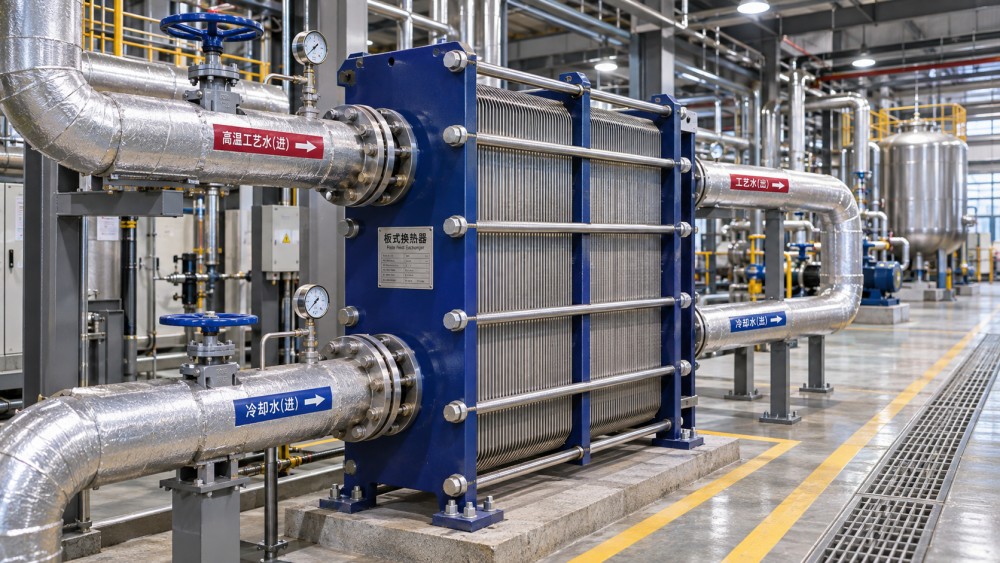
A plate heat exchanger passes fluids through alternating channels formed by thin, usually corrugated plates. Heat crosses the plate wall while the fluids remain separated. The geometry promotes mixing within the channels and provides substantial heat-transfer area in a compact volume. For suitable liquids, this can deliver the required duty with a smaller temperature driving force than some alternative designs.
A close temperature approach is valuable when the available waste heat is only moderately warmer than the stream that needs heating. It may allow more heat to be recovered before a boiler, electric heater, chiller, or cooling system supplies the remaining duty. In cooling applications, a suitable exchanger can also transfer heat to an available cooling medium and reduce mechanical cooling demand when conditions permit.
Compactness alone does not establish an efficiency gain. Heat transferred between two streams is not itself an energy saving unless it displaces a useful external load. A recovered kilowatt of heat may have a different economic value from a kilowatt of electricity used by a pump. Compare the actual utility changes at their respective costs and operating hours.
Start with the temperature profile, not the exchanger size
Before requesting a design, establish the inlet temperatures, required outlet temperatures, flow rates, and operating hours for both streams. Include normal, minimum, and maximum conditions. A design based only on a peak duty may perform poorly or create unnecessary pressure loss during the much longer periods spent at part load.
For an initial liquid-to-liquid estimate, calculate duty on each side using flow rate, specific heat capacity, and temperature change: Q = ṁ × cp × ΔT. Use consistent units and check whether the hot-side heat released reasonably matches the cold-side heat gained. Differences can indicate measurement error, heat loss, an overlooked bypass, or fluid properties that vary with temperature. Where phase change or strongly variable properties are involved, use an appropriate enthalpy balance instead.
Then examine the temperature difference at both ends of the exchanger. Countercurrent flow can support a close approach, but the hot stream must remain sufficiently warmer than the cold stream at each corresponding point. A very small approach generally requires more heat-transfer area and can make the design more sensitive to fouling and changing inlet conditions. Ask the supplier to show the temperature profile rather than accepting a single overall duty figure.
Timing matters as much as temperature. A hot stream available only during cleaning cannot continuously preheat a production stream unless suitable storage or scheduling connects them. Similarly, a heat source may be available all year while demand for recovered heat falls at certain times. Estimate useful recovery over the actual operating schedule, not from maximum simultaneous flow alone.
Pressure drop can consume the apparent saving
Narrow, turbulent channels improve heat transfer, but they also create resistance to flow. Adding plates, changing plate geometry, or using a different pass arrangement can change both thermal performance and pressure drop. The best thermal design on paper may require a pump upgrade or operate an existing pump outside its acceptable range.
Set an allowable pressure drop for each side using the full hydraulic system, not the exchanger in isolation. Account for piping, strainers, control valves, elevation where relevant, and a reasonable allowance for fouling. Check available pump head at the expected flow and confirm motor and variable-speed-drive limits across the operating range.
Estimate the additional electrical input from the exchanger pressure loss using flow rate and pressure drop, adjusted for pump and motor efficiencies. Compare annual pump electricity with the utility energy displaced. This is particularly important when the recovered temperature lift is small, electricity is costly relative to the displaced heat, or the exchanger operates for long periods at high flow.
Request performance at part load as well as design load. Control valves, bypasses, and changing fluid viscosity can alter the actual system pressure balance. A bypass may protect the process from overcooling or overheating, but it also reduces the fraction of flow receiving heat recovery; include its expected use in the annual calculation.
Fluid condition determines whether performance lasts
Clean, low-viscosity liquids are generally favorable candidates. Fine channels become less attractive when a stream contains fibers, large particles, crystallizing material, or deposits that cannot be removed by the available cleaning method. Fouling adds thermal resistance and can increase pressure drop, so a clean-unit rating alone is not enough for an operating decision.
Ask for a design that states the assumed fouling condition and cleaning basis. Fouling allowances should reflect the fluids and operating experience rather than an arbitrary margin. Excessive allowance can increase cost or lead to low channel velocities; too little can leave the exchanger unable to meet duty between cleaning intervals.
- Suspended solids: Establish particle size, concentration, and whether screening is practical without creating a separate maintenance bottleneck.
- Scaling and precipitation: Check whether wall temperatures, concentration, or mixing conditions encourage deposits, particularly on the hot side.
- Viscosity: Supply viscosity across the operating temperature range. A fluid that thickens as it cools may cause a much higher pressure drop than expected.
- Chemical compatibility: Assess plate and gasket materials against both process fluids and cleaning chemicals, including temperature and concentration.
Where contamination between streams would create a serious product, safety, or environmental consequence, evaluate the leakage path and pressure relationship. Depending on the application, double-wall construction, an intermediate loop, leak detection, or another exchanger type may be appropriate. These measures affect temperature approach, cost, and pumping demand, so they belong in the efficiency comparison rather than being added after selection.
Choose a construction that matches the maintenance plan
Gasketed plate-and-frame units can be opened for inspection and mechanical cleaning, and some designs allow the plate pack to be modified. That accessibility is useful when deposits are manageable but periodic inspection is necessary. It also requires sufficient space to open the frame and remove plates. Gaskets must be compatible with operating and cleaning conditions, and their replacement becomes part of lifecycle planning.
Brazed and welded plate exchangers eliminate some or all conventional gaskets and can be compact options for compatible duties. Many cannot be opened for mechanical cleaning, however, so fluid cleanliness, clean-in-place effectiveness, and the consequences of blockage deserve particular scrutiny. Construction limits vary by design; verify the actual pressure, temperature, fatigue, and material ratings rather than assuming that a construction type is suitable.
Shell-and-tube equipment may be preferable where solids handling, mechanical cleaning, pressure containment, or other service requirements outweigh a plate exchanger’s compactness and close-approach capability. Compare alternatives at the same process duty, inlet conditions, allowable pressure drops, and expected fouled performance. A smaller footprint or higher clean heat-transfer coefficient is not a like-for-like energy comparison.
Build the decision around annual net performance
When comparing heat exchange solutions, energy efficient operation should be evaluated over the operating cycle. Use the same time periods and utility assumptions for every option, and separate measured inputs from estimates that require confirmation. A practical evaluation can follow this sequence:
- Define the baseline. Record current heating, cooling, and pumping arrangements, including any heat already recovered. Identify which utility loads the proposed exchanger can actually displace.
- Divide operation into representative conditions. Include production rates, seasonal cooling-water temperatures, start-up, cleaning, and periods when only one stream is available.
- Calculate useful heat recovery. Apply each condition’s temperature, flow, and duration. Exclude recovered heat that has no simultaneous demand or cannot be stored economically.
- Subtract additional operating requirements. Include incremental pump electricity, changes to cooling or heating utilities, and any auxiliary equipment needed for the proposed arrangement.
- Price the lifecycle consequences. Add installed equipment, piping, controls, cleaning, replacement parts, downtime, and expected service. Compare the annual net benefit with the investment using the site’s financial criteria.
Run sensitivity checks on uncertain inputs. If the decision changes substantially with a modest variation in operating hours, fouling rate, or utility cost, obtain better measurements before committing. A temporary temperature and flow survey can be more valuable than refining a design around assumptions that have not been verified.
The final specification should ask suppliers for thermal duty, outlet temperatures, pressure drop on both sides, material selection, fouling assumptions, and cleaning requirements at the agreed conditions. Include minimum and maximum operating cases, not just the nominal point. The strongest candidate is the one that delivers useful recovery within hydraulic and maintenance constraints throughout the expected service interval—not simply the unit with the highest quoted clean-state duty.
Ready when you are. Send us a message to get started.
Related News
- When are plate heat exchangers an energy-efficient solution?Author :Thermodynamics Analyst

- How corrugation angle affects heat transfer in plate heat exchangersAuthor :Thermodynamics Analyst

- When do plate heat exchangers suit Middle East seawater cooling?Author :Thermodynamics Analyst

- When does gasketed plate heat exchanger technology suit your process?Author :Thermodynamics Analyst

- When does heat recovery improve data center cooling efficiency?Author :Thermodynamics Analyst

- How Do I Verify Heat Transfer Calculations in a Supplier Quotation?Author :Thermodynamics Analyst

- How to evaluate a plate heat exchangers supplier before orderingAuthor :Thermodynamics Analyst

- EU Tightens Fatigue Checks for Plate Heat ExchangersAuthor :Thermodynamics Analyst

- EU PFAS Rule Adds New Export Filing for Cooling EquipmentAuthor :Thermodynamics Analyst

- EU EN 13445-4:2026 Adds Fatigue Report RequirementAuthor :Thermodynamics Analyst

- EU Updates EN 13445-4 for Plate ExchangersAuthor :Thermodynamics Analyst

- How to Compare Energy-Efficient Heat Exchange SolutionsAuthor :Thermodynamics Analyst

- Brazed Plate Exchanger Design: 7 Factors That Affect Heat TransferAuthor :Thermodynamics Analyst

- EU CBAM Pilot List Adds Plate ExchangersAuthor :Thermodynamics Analyst

- How Heat Exchange Systems Improve Temperature Control StabilityAuthor :Thermodynamics Analyst

- Japan to Require Efficiency Labels for Plate ExchangersAuthor :Thermodynamics Analyst

- EU REACH Adds PFAS Ban for Plate Heat ExchangersAuthor :Thermodynamics Analyst

- India Enforces BIS Rule for Plate Heat ExchangersAuthor :Thermodynamics Analyst

- DIN EN 13445-6:2026 Tightens Plate Exchanger CE RulesAuthor :Thermodynamics Analyst

- EU REACH Restricts PFAS Seals for Plate Heat ExchangersAuthor :Thermodynamics Analyst

- India Mandates BIS Certification for Imported Plate ExchangersAuthor :Thermodynamics Analyst

- Vietnam Requires QR Labels on Imported Plate Heat ExchangersAuthor :Thermodynamics Analyst

- EU EN 13445-4:2026 Tightens NDT Rules for Heat ExchangersAuthor :Thermodynamics Analyst

- EPA Clears R-1234ze(E) for Plate Exchanger SystemsAuthor :Thermodynamics Analyst
 for Plate Exchanger Systems")
- Heat Exchange Equipment Selection: Key Performance Checks Before You Compare ModelsAuthor :Thermodynamics Analyst

- ASHRAE 90.1-2026 Raises Plate Exchanger Efficiency ThresholdAuthor :Thermodynamics Analyst

- Heat Exchange Systems: How to Choose the Right SetupAuthor :Thermodynamics Analyst

- EPA SNAP 89 Takes Effect for Plate ExchangersAuthor :Thermodynamics Analyst

- How to Compare Heat Exchange Solutions for Lower Energy UseAuthor :Thermodynamics Analyst

- EPA SNAP 89 Expands Filing Rules for Plate Heat ExchangersAuthor :Thermodynamics Analyst

- EPA SNAP update adds filing rule for plate heat exchangersAuthor :Thermodynamics Analyst

- Industrial Heat Recovery: Where the Payback Is Fastest in 2026Author :Thermodynamics Analyst

- California EPR Deadline Nears for Cooling Equipment MakersAuthor :Thermodynamics Analyst

- Heat Exchanger Technology: Plate vs Shell and Tube for EfficiencyAuthor :Thermodynamics Analyst

- Industrial Heat Recovery Options for High-Temperature ProcessesAuthor :Thermodynamics Analyst

- Heat Transfer Problems in Process Lines: Causes and Practical FixesAuthor :Thermodynamics Analyst


