


How to choose a cooling solution for a high-power PCB




Choosing a cooling solution for a high-power PCB requires more than matching a heat sink to the hottest component. Thermal load, hotspot location, airflow, available space, and operating conditions all affect reliability and performance. For technical evaluators comparing electronics cooling solutions PCB designers can implement, the decision starts with a clear picture of where heat is generated and how it can leave the assembly. The best choice is not necessarily the most aggressive cooling technology; it is the one that maintains safe temperatures across the required operating envelope without creating unacceptable cost, power consumption, or integration risk.
Start with the heat path, not the heat sink
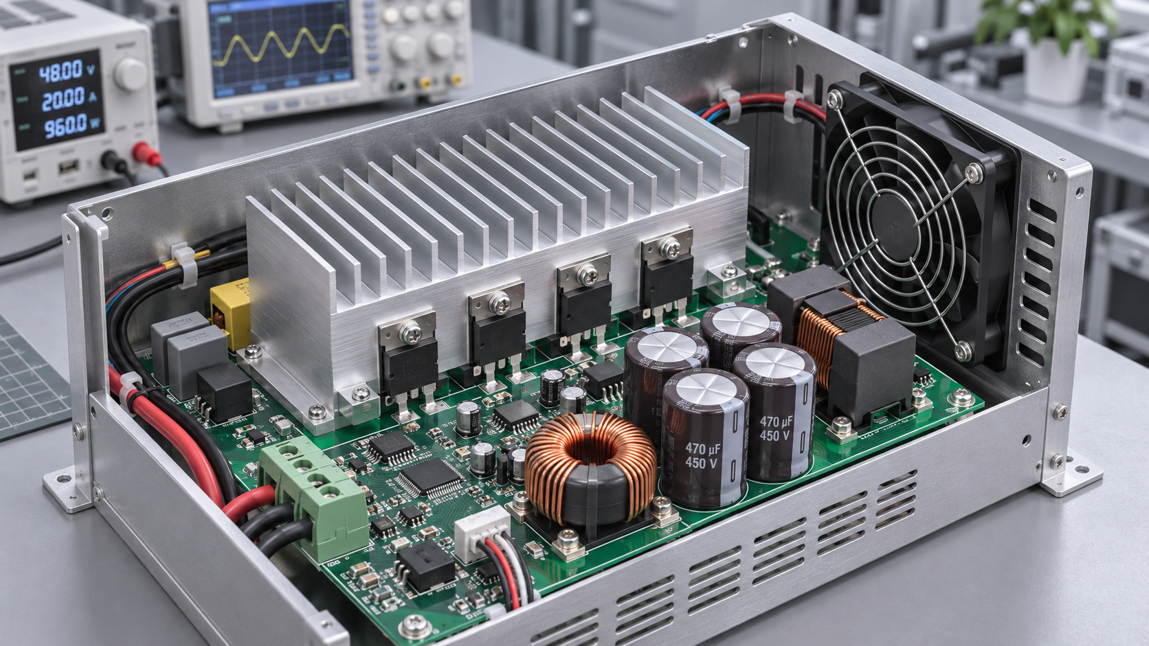
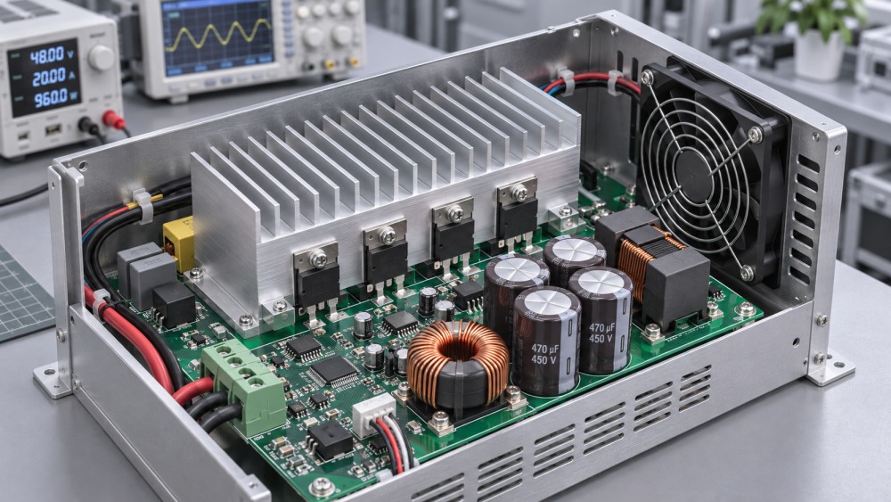
A power board may contain several very different thermal problems. A switching transistor can produce an intense local hotspot, while inductors, capacitors, connectors, and copper traces add heat over a wider area. Cooling the transistor successfully does not automatically protect a nearby capacitor from elevated ambient temperature.
Build a thermal inventory before comparing hardware. For each significant heat source, identify its expected power dissipation, location, temperature limit, and operating duty cycle. Use losses rather than input power: a device handling hundreds of watts may dissipate only a fraction of that power as heat. Include worst-case combinations of electrical load, switching conditions, and environmental temperature, rather than assuming that the normal operating point is sufficient.
Then trace the likely route from each heat source to the surrounding environment. Heat may travel through a package into a heat sink, through solder and copper into the PCB, or into a chassis through a thermal interface. The limiting resistance can occur at any point along that route. A larger heat sink offers little benefit if heat cannot reach it effectively.
Turn temperature limits into a usable thermal budget
For a preliminary estimate, compare the maximum permitted component temperature with the temperature of the cooling medium. For a component dissipating power P, a simplified total thermal resistance budget is:
Rθ,total = (Tlimit − Tambient) / P
If a component dissipates 20 W, its applicable temperature limit is 125°C, and the air entering the cooling path may reach 45°C, the theoretical budget is 4°C/W. That budget covers the complete path from the component’s temperature reference point to the cooling air, including the package, interface, heat spreader or sink, and convection. It is not a target for the heat sink alone.
In practice, reserve margin for measurement uncertainty, aging, manufacturing variation, and operating excursions. Verify whether the specified limit is a junction, case, or surface temperature; those values are not interchangeable. Datasheet thermal resistance figures are also conditional on the stated test setup and may not predict performance on a different board or in a confined enclosure.
For shared heat sinks or densely packed components, individual budgets are only a starting point. Neighboring devices can raise local air and surface temperatures, so the temperatures must ultimately be assessed together.
Compare cooling approaches against the actual constraints
The following options can be combined. A board may use copper spreading under its power devices, a chassis interface for bulk heat removal, and a fan to prevent heat from accumulating around sensitive components.
When board-level conduction is enough—and when it is not
Copper planes and thermal vias can distribute heat away from exposed pads and reduce local temperature gradients. Their effectiveness depends on the complete construction: copper thickness, plane area, via geometry, layer connectivity, solder coverage, and the way heat exits the board. Adding vias beneath a device helps only if the connected copper has somewhere useful to send the heat.
This approach becomes less convincing when a small component produces a concentrated load or when a compact enclosure allows the entire board to heat up. In those cases, use the PCB as part of a wider path to a heat sink, metal enclosure, or other heat-rejection surface. Check electrical isolation and clearance requirements before attaching conductive hardware.
Air cooling: evaluate the path, not the fan rating
A fan’s free-air flow rating does not describe what the board will receive once filters, grilles, cables, heat-sink fins, and other restrictions are installed. The operating point depends on the fan curve and the pressure losses of the complete airflow path. Recirculation can also send warmed exhaust air back toward the inlet.
For natural convection, orientation and spacing matter because buoyancy-driven flow needs an unobstructed route. For forced convection, verify that air actually reaches the hotspots instead of bypassing them. A duct, baffle, or repositioned component can sometimes improve the result more effectively than specifying a larger fan.
Consider what happens after deployment. Dust loading can increase resistance and reduce airflow; fan degradation or failure may turn a comfortable design into a thermal shutdown. Decide whether the application needs fan monitoring, redundancy, filtering, a cleaning interval, or a controlled power derating strategy.
Liquid cooling and heat transport devices
A cold plate can move substantial heat out of a confined electronics enclosure, but it shifts part of the problem to the coolant loop and its external heat exchanger. Evaluate the full system: pump power, coolant inlet temperature, flow distribution, pressure drop, materials compatibility, condensation risk, and service access. A low component temperature in a laboratory test is not enough if the facility cannot maintain the assumed coolant conditions.
Heat pipes and vapor chambers solve a different problem: they transport or spread heat toward a remote surface. They do not eliminate the need for a heat sink, chassis, or liquid loop to reject that heat. Confirm the supplier’s operating limits and orientation guidance for the intended installation.
The interface can decide the outcome
Thermal interface materials fill microscopic gaps between mating surfaces, but they introduce resistance of their own. Grease, pads, gap fillers, and phase-change materials differ in thickness, compliance, electrical properties, and assembly requirements. A high nominal conductivity does not guarantee a low installed resistance if the material is too thick, poorly applied, or compressed incorrectly.
Review flatness, mounting pressure, fastener tolerances, surface cleanliness, and the manufacturer’s application instructions. If electrical isolation is required, include the insulating layer in the thermal budget. Also check whether the assembly can tolerate vibration, thermal cycling, rework, and changes in contact pressure over its intended life.
Mechanical stress deserves equal attention. A stiff heat sink or chassis connection can bend the PCB or load solder joints if tolerances are poorly controlled. Thermal performance should be assessed alongside the mechanical design, not added after the enclosure is frozen.
Validate the candidate in the enclosure
Simulation and hand calculations narrow the field, but a representative physical test is essential. Test the complete assembly with production-intent interfaces, covers, airflow restrictions, mounting hardware, and neighboring heat sources. Include the highest specified inlet-air or coolant temperature and the electrical operating conditions that create the greatest credible thermal stress.
Place measurements where they answer design questions: at critical component cases or accessible reference points, near air inlets and exhausts, on heat-sink bases, and at interfaces where temperature drops may be significant. Thermocouples can disturb small measurement sites, while infrared readings require attention to emissivity and reflections. Neither method directly measures an inaccessible semiconductor junction; use an appropriate manufacturer-supported method or model when junction temperature must be established.
Allow the assembly to reach an appropriate steady state for continuous operation, and examine transient behavior for short-duration peaks. A design may pass an average-load test yet exceed a junction limit during repeated bursts. Conversely, testing only a brief peak can exaggerate the need for cooling if the real duty cycle and heat capacity are well understood.
Before approval, evaluate foreseeable degraded conditions: reduced airflow from a loaded filter, a failed fan where relevant, elevated coolant temperature, or blocked ventilation. Record the assumptions behind each result so that a later enclosure or component change triggers the right reassessment.
Make the trade-off explicit
When two electronics cooling solutions for a PCB both meet the temperature target, compare them at system level. A passive assembly may use more space but avoid fan power and maintenance. Forced air may reduce heat-sink size while adding noise and a service dependency. A cold plate may solve a severe hotspot but introduce a pump, coolant connections, and leak-control requirements.
A practical selection record should state:
- The critical temperature limits, heat loads, environmental conditions, and safety margins used.
- The measured or modeled temperatures at relevant worst-case and degraded operating points.
- Power consumption, space, mass, acoustic limits, and effects on neighboring components.
- Manufacturing controls for interfaces, mounting pressure, and assembly tolerances.
- Expected inspection or maintenance needs and the response to cooling-system failure.
Choose the simplest arrangement that satisfies those requirements with defensible margin. That decision may change as enclosure geometry, power density, energy costs, or available cooling infrastructure change. Reviewing the complete heat path—and documenting the assumptions behind it—gives evaluators a sound basis for comparing designs long after the first prototype leaves the test bench.
Ready when you are. Send us a message to get started.
Related News
- Can skid-mounted thermal integration reduce plant energy use?Author :

- Cybersecurity Firm Detects Login Attempts Targeting Danfoss Refrigeration ControllersAuthor :

- How to choose a cooling solution for a high-power PCBAuthor :

- EU Monitors Cyberattacks on European Supermarket Refrigeration SystemsAuthor :

- How to assess a pure power source manufacturer's voltage stabilityAuthor :

- EHPA Seeks Inclusion of Heat Pumps in €175 Billion EU Research PlanAuthor :

- US to Lift 50% Tariff on Some Canadian Refrigeration EquipmentAuthor :

- Chillventa 2026 Sets Records for Exhibitor and Visitor NumbersAuthor :

- Carrier Plans $600 Million Manufacturing and Engineering Center in Fort WorthAuthor :

- Semiconductor Thermal Management: Low Vibration Design PrioritiesAuthor :

- Thermal Interface Materials: What Drives Real Thermal OptimizationAuthor :
![]()
- Global Energy Costs in Europe: What Changed in 2026Author :

- Smart Device Thermal Management: Common Failures and FixesAuthor :

- Thermal Efficiency Optimization: 5 Signs Your System Is Losing HeatAuthor :

- How Precision Temperature Control Systems Improve Process StabilityAuthor :

- How Intellectualization Improves Process Visibility in Modern PlantsAuthor :

- Global Energy Costs in 2026: What Rising Prices Mean for Plant PlanningAuthor :

- Carbon Neutrality Roadmaps: Common Gaps in Industrial PlanningAuthor :

- Heat Transfer Basics: What Affects Efficiency in Industrial EquipmentAuthor :

- Industrial Thermal Systems: Common Failure Risks in Continuous OperationAuthor :

- Global Energy Costs: 2026 Risk Signals to WatchAuthor :

- Pneumatic Power Systems: Common Sizing Mistakes to AvoidAuthor :

- How Thermal Power Systems Cut Downtime in 2026Author :

- Clean Energy Technology Trends Reshaping Industry in 2026Author :

- Pneumatic Power Systems: Key Checks Before Equipment SelectionAuthor :

- Compression Technology Mistakes That Raise Maintenance RiskAuthor :

- Clean Energy Technology Risks to Watch in 2026 ProjectsAuthor :

- Smart Thermal Systems: 5 Signals Your Controls Are Wasting HeatAuthor :

- How to Size Pneumatic Power Systems for Stable OutputAuthor :

- Pneumatic Power Systems: Key Safety Risks in Daily OperationAuthor :

- Clean Energy Technology Shifts Reshaping Industrial InvestmentAuthor :

- Intellectualization in Industry: What Delivers Measurable Value?Author :

- Thermal Management Mistakes That Shorten Equipment LifeAuthor :

- Clean Energy Technology Options That Fit Real Manufacturing UpgradesAuthor :

- Energy-Saving Technologies Worth Tracking in 2026Author :