Pneumatic Power Systems: Common Sizing Mistakes to Avoid




In pneumatic power systems, sizing errors can quietly undermine efficiency, reliability, and lifecycle cost long before problems become visible on the production floor. For technical evaluators, understanding the most common sizing mistakes is essential to selecting equipment that matches real operating demand, avoids energy waste, and supports stable performance across compressed air applications.
Across manufacturing, packaging, process control, electronics, food handling, and utility operations, even a small mismatch in compressor flow, receiver volume, line diameter, or pressure setting can create recurring losses. In many facilities, the issue is not system failure on day 1, but a 12 to 36 month decline in efficiency, rising maintenance calls, and unstable end-use pressure.
For technical assessment teams, pneumatic power systems should be evaluated as complete operating networks rather than as isolated compressor packages. Correct sizing depends on demand variability, duty cycle, pressure band, air quality class, future expansion, and the interaction between compression, storage, treatment, and distribution components.
Why Sizing Errors Persist in Pneumatic Power Systems
Sizing mistakes remain common because many projects still rely on nameplate assumptions, peak estimates, or legacy equipment replacement logic. A plant may replace a 75 kW compressor with another 75 kW unit without confirming whether actual flow demand is 8%, 25%, or even 40% different from the original design basis.
In pneumatic power systems, the true load profile often shifts by season, shift pattern, product mix, and automation level. A line operating 2 shifts today may move to 3 shifts within 6 months, while another process may have intermittent bursts lasting 20 to 90 seconds that are invisible in monthly utility averages.
The cost of getting the numbers wrong
Oversizing usually looks safe during procurement, but it often drives poor part-load efficiency, more unload cycles, and higher specific energy consumption. Undersizing, by contrast, causes pressure instability, nuisance alarms, production slowdowns, and accelerated wear on compressors, dryers, valves, and point-of-use actuators.
In practical terms, a pressure drop increase of just 0.5 to 1.0 bar can force operators to raise compressor discharge pressure. That decision may seem minor, yet over a full year it can materially increase energy use and reduce the stability margin for downstream pneumatic tools and automation devices.
Where technical evaluators should focus first
- Measure average and peak air demand over at least 7 to 14 operating days.
- Separate continuous load from intermittent demand events above 10 seconds.
- Confirm pressure requirements at the point of use, not only at the compressor outlet.
- Check whether future capacity expansion of 10% to 30% is realistic or speculative.
This distinction matters because many pneumatic power systems are oversized for uncertain expansion that never arrives, while others are undersized because hidden users, leakage, or simultaneous machine starts were excluded from the assessment model.
The Most Common Sizing Mistakes to Avoid
The following mistakes appear repeatedly in industrial compressed air projects. They affect capital cost, energy use, service interval stability, and equipment life. For technical evaluators, each one should be reviewed during specification, supplier comparison, and site acceptance planning.
1. Using peak demand as the only sizing basis
A system designed entirely around the highest short-duration peak often ends up oversized for 80% to 95% of operating hours. Instead, evaluators should classify demand into base load, variable load, and transient peaks, then assign compressor, receiver, and control logic roles accordingly.
In many pneumatic power systems, a larger air receiver or a secondary trim machine can manage a 30-second surge more efficiently than installing one oversized fixed-speed compressor. That approach usually improves control stability and reduces unload losses during normal production periods.
A more reliable approach
- Record real demand at 1-second to 5-second intervals.
- Identify sustained load bands lasting more than 15 minutes.
- Size base capacity for the dominant load band.
- Use storage or trim capacity for brief peaks.
2. Ignoring pressure drop across the system
Flow sizing without distribution analysis is one of the most expensive errors in pneumatic power systems. Pipes, filters, dryers, separators, hoses, quick couplings, and aging distribution branches all add pressure loss. If a tool needs 6.0 bar at the point of use, a compressor discharge setting of 6.2 bar may be inadequate once the full line is loaded.
Technical evaluators should map pressure drop from the compressor room to the critical end user. A typical design target is to keep total system pressure loss within a controlled band, often around 0.3 to 0.7 bar depending on process sensitivity, line length, and air treatment configuration.
The table below highlights common sizing mistakes, the technical effect they create, and the practical correction path during evaluation and procurement.
The key lesson is that sizing is not only about compressor capacity. In pneumatic power systems, effective sizing is the combined result of flow, pressure, storage, treatment, control strategy, and distribution resistance.
3. Underestimating receiver tank requirements
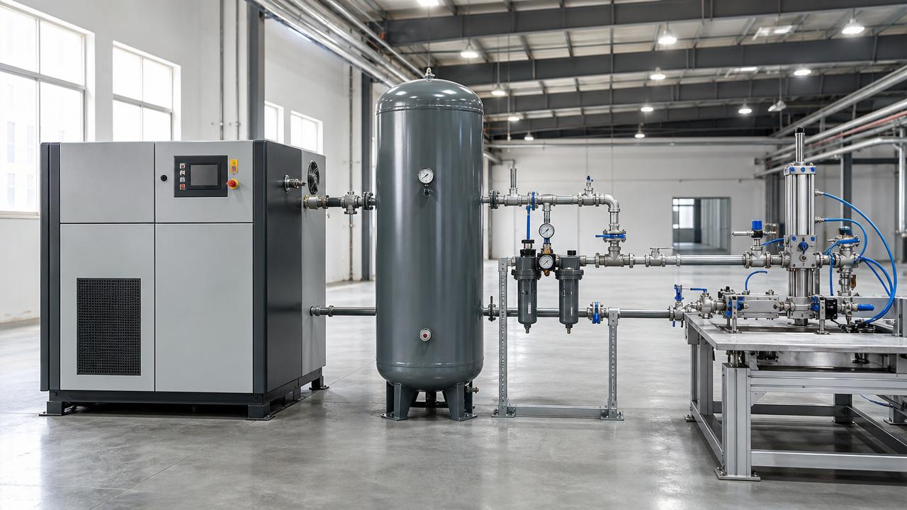
Receiver volume is often treated as a standard accessory rather than a control component. That is a mistake. A properly sized receiver helps smooth flow spikes, reduce compressor cycling, stabilize pressure, and improve dryer and filter performance during fluctuating demand.
While exact receiver sizing depends on control philosophy and pressure band, technical evaluators should review whether the selected volume can absorb transient events lasting 10 to 60 seconds without pushing the compressor into unstable cycling. A tank that is too small can create repeated starts, wider pressure swings, and unnecessary wear.
4. Failing to account for air treatment pressure and flow losses
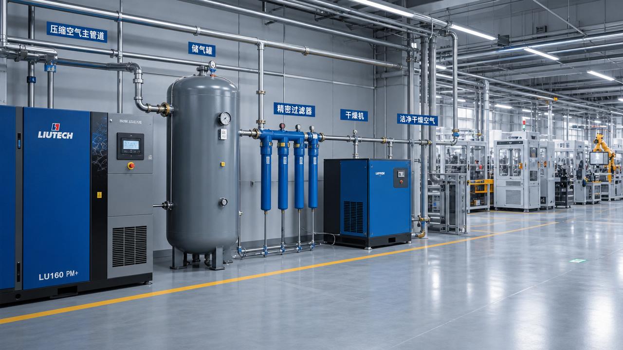
Dryers, coalescing filters, particulate filters, drains, and separators all influence sizing. In high-purity applications such as pharmaceutical packaging, food handling, instrumentation, or semiconductor support processes, air treatment is not optional, and every stage adds resistance or operating constraints.
A common error is sizing the compressor for nominal flow but selecting filters that create excessive differential pressure once partially loaded. Another is choosing a dryer based on ideal inlet conditions even though summer ambient temperatures, aftercooler performance, and moisture load can shift the operating envelope by 10% to 20%.
How to Size Pneumatic Power Systems More Accurately
A practical sizing method should combine field measurement, process understanding, and procurement discipline. For technical evaluators, the goal is not to eliminate all uncertainty, but to reduce the risk of structural mismatch before equipment is ordered or retrofitted.
Build the demand profile in layers
Start with a 3-layer demand model. Layer 1 is stable base consumption, Layer 2 is recurring variable demand, and Layer 3 is short-duration peaks. This simple structure is often more useful than relying on one average flow number and one maximum flow number.
For many plants, at least 5 operating variables should be reviewed: shift pattern, simultaneous machine use, maintenance bypass demand, leakage level, and planned line expansion. If any one of these variables changes by more than 15%, the selected sizing basis may need adjustment.
Check point-of-use conditions, not just compressor room data
Pneumatic power systems are judged by what happens at cylinders, valves, tools, air knives, packaging heads, and process instruments. A system that looks acceptable at the compressor room can still fail if remote users see unstable pressure, wet air, or poor recovery after a pressure event.
In long distribution systems, evaluators should inspect branch piping, dead legs, pipe diameter changes, and local regulators. Even one undersized branch can compromise the effective capacity delivered to a critical production cell.
The table below provides a practical review framework that technical evaluators can use before approving a pneumatic power systems specification or supplier proposal.
This framework helps teams compare supplier proposals on consistent technical grounds. It also reduces the risk of selecting equipment based only on motor size, catalog flow, or the lowest initial quotation.
Include leakage and maintenance realities
Leakage is frequently ignored during sizing reviews, yet many industrial networks lose a meaningful share of compressed air through fittings, drains, seals, and aging hoses. If leakage is not separated from productive demand, technical evaluators may approve unnecessary capacity instead of recommending leak correction first.
Maintenance condition also matters. Filter fouling, drain failure, cooling degradation, and valve wear can shift system performance over a 6 to 12 month period. A design with no operating margin may perform acceptably during commissioning but become unstable well before the next budget cycle.
Procurement and Risk-Control Guidance for Technical Evaluators
When pneumatic power systems move from engineering review to procurement, documentation quality becomes critical. Many sizing disputes arise not because equipment is inherently poor, but because suppliers and buyers used different assumptions for flow units, operating pressure, ambient condition, or required air quality.
Questions to ask before approval
- Is stated flow delivered at the actual operating pressure or only at reference conditions?
- Does the proposal define continuous demand, intermittent demand, and emergency reserve separately?
- Are filter and dryer pressure losses included at clean and loaded conditions?
- What happens if production expands by 15% within the next 12 months?
- Can the control strategy maintain stability across low-load and peak-load periods?
Documentation that improves decision quality
A strong evaluation file for pneumatic power systems should include a demand log, pressure map, equipment schedule, treatment train description, and a simple risk note covering 3 to 5 failure scenarios. This level of documentation makes later troubleshooting faster and improves internal approval confidence.
For organizations comparing multiple vendors, it is useful to request a common response template. That template should define flow units, reference conditions, noise limits, maintenance intervals, control type, and the assumptions behind any recommended storage volume. Standardized inputs often reveal where proposals differ in substance rather than in formatting.
Why industry intelligence matters
Technical evaluators increasingly work under pressure to balance uptime, sustainability, and capital discipline. In that environment, decision support from industry intelligence platforms such as GTC-Matrix becomes valuable because compressor selection, treatment design, and thermal performance are closely linked to energy cost trends, decarbonization targets, and process reliability expectations.
For sectors that depend on clean compressed air and stable thermal control, including pharmaceuticals, semiconductors, and food processing, sizing decisions are not only engineering choices. They influence operating cost, product consistency, maintenance planning, and future compliance readiness.
Avoiding common sizing mistakes in pneumatic power systems requires more than a larger safety factor. It requires measured demand data, point-of-use pressure verification, realistic storage planning, and a disciplined review of treatment and distribution losses. For technical evaluators, these steps improve specification accuracy and reduce lifecycle risk across compressed air applications.
If your team is reviewing compressor capacity, air treatment layout, or full-system efficiency strategy, GTC-Matrix can help you translate technical complexity into clearer decision criteria. Contact us to explore tailored intelligence support, compare solution pathways, and learn more about practical pneumatic power systems optimization.
Ready when you are. Send us a message to get started.
Related News
- Carrier Plans $600 Million Manufacturing and Engineering Center in Fort WorthAuthor :

- Semiconductor Thermal Management: Low Vibration Design PrioritiesAuthor :

- Thermal Interface Materials: What Drives Real Thermal OptimizationAuthor :
![]()
- Global Energy Costs in Europe: What Changed in 2026Author :

- Smart Device Thermal Management: Common Failures and FixesAuthor :

- Thermal Efficiency Optimization: 5 Signs Your System Is Losing HeatAuthor :

- How Precision Temperature Control Systems Improve Process StabilityAuthor :

- How Intellectualization Improves Process Visibility in Modern PlantsAuthor :

- Global Energy Costs in 2026: What Rising Prices Mean for Plant PlanningAuthor :

- Carbon Neutrality Roadmaps: Common Gaps in Industrial PlanningAuthor :

- Heat Transfer Basics: What Affects Efficiency in Industrial EquipmentAuthor :

- Industrial Thermal Systems: Common Failure Risks in Continuous OperationAuthor :

- Global Energy Costs: 2026 Risk Signals to WatchAuthor :

- Pneumatic Power Systems: Common Sizing Mistakes to AvoidAuthor :

- How Thermal Power Systems Cut Downtime in 2026Author :

- Clean Energy Technology Trends Reshaping Industry in 2026Author :

- Pneumatic Power Systems: Key Checks Before Equipment SelectionAuthor :

- Compression Technology Mistakes That Raise Maintenance RiskAuthor :

- Clean Energy Technology Risks to Watch in 2026 ProjectsAuthor :

- Smart Thermal Systems: 5 Signals Your Controls Are Wasting HeatAuthor :

- How to Size Pneumatic Power Systems for Stable OutputAuthor :

- Pneumatic Power Systems: Key Safety Risks in Daily OperationAuthor :

- Clean Energy Technology Shifts Reshaping Industrial InvestmentAuthor :

- Intellectualization in Industry: What Delivers Measurable Value?Author :

- Thermal Management Mistakes That Shorten Equipment LifeAuthor :

- Clean Energy Technology Options That Fit Real Manufacturing UpgradesAuthor :

- Energy-Saving Technologies Worth Tracking in 2026Author :