


How to assess a pure power source manufacturer's voltage stability




A credible voltage-stability assessment starts with a practical question: can the power source keep voltage within the load’s acceptable limits at the point of use, through the operating conditions that matter? A tight regulation figure is useful, but it does not establish how the output behaves during a sudden load change, an input disturbance, or a temperature rise.
When comparing a pure power sources manufacturer with other suppliers, ask for a defined test method and evidence from a representative unit. The strongest comparison connects steady-state accuracy, transient response, and electrical noise to the actual load. A source that performs well on a resistive bench load may behave differently when connected to a pulsed process tool, a motor drive, or a distributed system with long cables.
Start with the voltage tolerance at the load
Before reviewing supplier specifications, establish what the equipment being powered can tolerate. Record the nominal voltage and acceptable range at its input terminals, along with normal operating current, peak current, load-change rate, and any periods of low or no load. For an AC source, include frequency and phase requirements where applicable. For a DC source, identify any startup, shutdown, or output-sequencing constraints.
Separate limits by duration. A process may tolerate a brief excursion that would be unacceptable if sustained, while another load may be sensitive to a short voltage dip even though the average remains within range. Equipment documentation may specify some of these limits; where it does not, the evaluator should agree on acceptance criteria with the equipment owner before comparing suppliers.
Also identify where the voltage must be controlled. A manufacturer may specify regulation at the power source terminals, but the load sees voltage after cable resistance, connectors, distribution devices, and switching components. A stable source output can still produce an unacceptable voltage at the equipment input during a high-current event. If remote sensing is proposed to compensate for cable drop, check the permitted sense-lead arrangement, compensation range, and behavior if a sense wire is disconnected.
Define the anticipated input supply as well: voltage range, frequency where relevant, and any disturbances that the source must ride through. Avoid assuming that a unit rated for a broad input range maintains identical output performance across that entire range.
Read regulation figures with their test conditions
Voltage regulation describes how much the output changes under specified conditions. Two figures appear frequently, but they answer different questions:
- Line regulation: output variation as the input voltage changes, with other stated conditions held constant.
- Load regulation: output variation as load current changes over a stated range, with other conditions held constant.
Neither figure is directly comparable across suppliers unless the reference conditions match. Check the input range, load range, output setting, temperature, measurement location, and whether the result is expressed as an absolute voltage or a percentage. A percentage also needs a stated reference value: a figure relative to full-scale output is not necessarily equivalent to one relative to the set voltage.
Initial set-point accuracy, temperature drift, and longer-term drift deserve separate attention. A source can regulate closely after warming up yet sit away from the desired set point. Conversely, a well-calibrated unit can drift as its surroundings heat up. Ask whether stated limits apply to a fully warmed unit, across the specified ambient range, and to every delivered unit or only to a typical design.
For an AC source, establish whether voltage is specified as RMS, and over what measurement interval. A stable RMS reading alone does not establish that the waveform is clean or that individual cycles remain within the load’s tolerance. Where waveform shape matters, evaluate distortion and cycle-level behavior alongside RMS regulation. For DC, a stable average reading can similarly conceal ripple or brief excursions.
Comparison rule: put each supplier’s claimed limit beside its operating conditions. If a condition is missing, request it before ranking the figures. A smaller number measured under easier conditions is not necessarily the better result.
Examine response to changing load and input
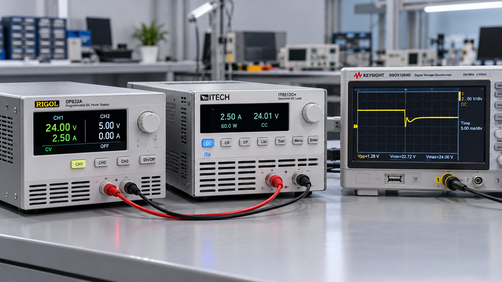
Steady-state regulation tells only part of the story. When load current changes abruptly, output voltage may dip or overshoot before the control system settles. The size and duration of that excursion can matter more than the final regulated value, particularly for sensitive controls or equipment with pulsed demand.
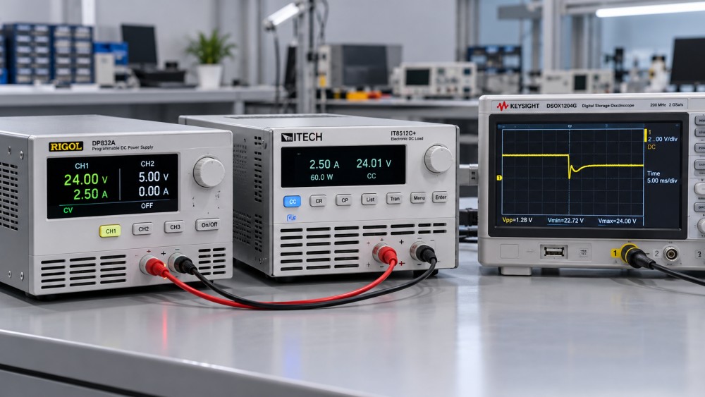
Request transient plots for load steps that resemble the application. Each plot should identify the starting and ending current, current slew rate, output voltage setting, input condition, temperature, measurement point, and time scale. A statement such as “fast recovery” has little evaluation value without a recovery band: settling within a loose band will occur sooner than settling within a tight one.
Review both directions of the step. A sudden increase in load can produce a voltage dip; a decrease can produce an overshoot. The relevant result is not just the largest excursion but also how long the load remains outside its allowable range and whether the output oscillates before settling. If the process has repeated pulses, a single isolated step may not represent the thermal or control behavior under a sustained pulse train.
Apply the same discipline to input disturbances. If incoming voltage sags or fluctuates, ask for output behavior at the expected input limits and during the disturbances the installation is designed to tolerate. Ride-through claims need a defined input event, load level, and output acceptance band. A source may remain powered during a sag without keeping its output within the process limit.
For systems with motors, compressors, heaters, or other switched loads, test the conditions created by those loads rather than relying only on a generic step test. Their inrush, switching sequence, and operating cycle can be more important than average demand. Ensure the power source is rated for the peak demand and that any current limit or protection mode will not create an unacceptable voltage collapse.
Measure ripple and noise without mistaking the setup for the source
Ripple and noise are voltage variations superimposed on the intended output. Their relevance depends on the load: a control circuit, measurement system, and high-power actuator may have very different sensitivity to amplitude and frequency. Ask the equipment owner which disturbance levels and frequency ranges affect operation, then match the supplier’s measurement to that requirement.
A ripple figure needs a bandwidth, measurement location, load condition, and measurement method. Peak-to-peak and RMS values describe different properties and should not be compared as though they were interchangeable. A bandwidth-limited measurement can be useful for a defined requirement, but it may omit higher-frequency components that matter to a particular load.
Probe technique matters. Long oscilloscope ground leads, cable routing, and nearby switching equipment can add apparent noise to the measurement. Use suitable probes and a documented setup, and check the instrument’s bandwidth and noise floor against the limit being assessed. For AC systems, distinguish waveform distortion from high-frequency noise; for DC systems, distinguish ripple from transient excursions. Each may require a different measurement and acceptance criterion.
Measure at the source terminals and, when feasible, at the load input. The difference can reveal voltage drop or disturbances introduced by the distribution path. If filtering or additional capacitance is needed at the load, include it in the representative test and verify that the source permits that connected load. Added capacitance can affect startup, inrush, and control-loop stability.
Make the comparison reproducible
A useful supplier evaluation combines documentation review with a witnessed or independently performed test on a representative unit. Agree on the test sequence before the equipment is assessed, including the configuration, warm-up condition, pass/fail limits, instrumentation, and treatment of measurement uncertainty. If the supplier cannot reproduce the application load exactly, document the differences and their likely effect on the result.
The evidence package should make it possible to trace each result to a unit and configuration. Request the model and options tested, firmware or control configuration where relevant, calibration status of instruments, raw or clearly scaled waveforms, and a record of ambient and input conditions. A short certificate stating that a unit passed inspection may support quality review, but it does not replace the underlying stability results for the conditions that drive the selection.
A focused acceptance sequence can cover the main decision points:
- Measure output at the required settings after the agreed warm-up period, at low, normal, and maximum intended load.
- Repeat steady-state measurements at relevant input and ambient limits, allowing conditions to stabilize.
- Apply representative load increases, decreases, and repeated pulses; capture both voltage and current waveforms.
- Measure ripple or waveform quality using the agreed bandwidth and technique, at the source and the point of use where practical.
- Exercise startup, shutdown, current limiting, and recovery from specified disturbances when these could affect the process.
Pass/fail limits should reflect the load, not merely repeat the supplier’s published specification. Leave room for cable losses, instrumentation uncertainty, operating variation, and any allowable drift between calibration intervals. If the available margin is small, test results close to the boundary should prompt further engineering review rather than an automatic pass.
Decide what the evidence actually supports
Compare suppliers by application-relevant outcomes: voltage range at the load, worst observed transient against the permitted duration, noise within the relevant measurement band, and performance across the agreed input and temperature conditions. Treat a typical curve as evidence of behavior, not as a guaranteed limit for every unit. Where a result is guaranteed, check its exclusions and whether it applies across the full intended operating range.
A manufacturer is easier to assess when its specifications, test conditions, and delivered configuration align. Unexplained gaps, such as a transient claim without a load-step definition or a regulation claim measured only at the source terminals, do not prove poor performance. They do limit what can be concluded. Resolve those gaps with a representative test or keep them visible as a qualification condition before the source is released for the process.
Ready when you are. Send us a message to get started.
Related News
- How to assess a pure power source manufacturer's voltage stabilityAuthor :

- EHPA Seeks Inclusion of Heat Pumps in €175 Billion EU Research PlanAuthor :

- US to Lift 50% Tariff on Some Canadian Refrigeration EquipmentAuthor :

- Chillventa 2026 Sets Records for Exhibitor and Visitor NumbersAuthor :

- Carrier Plans $600 Million Manufacturing and Engineering Center in Fort WorthAuthor :

- Semiconductor Thermal Management: Low Vibration Design PrioritiesAuthor :

- Thermal Interface Materials: What Drives Real Thermal OptimizationAuthor :
![]()
- Global Energy Costs in Europe: What Changed in 2026Author :

- Smart Device Thermal Management: Common Failures and FixesAuthor :

- Thermal Efficiency Optimization: 5 Signs Your System Is Losing HeatAuthor :

- How Precision Temperature Control Systems Improve Process StabilityAuthor :

- How Intellectualization Improves Process Visibility in Modern PlantsAuthor :

- Global Energy Costs in 2026: What Rising Prices Mean for Plant PlanningAuthor :

- Carbon Neutrality Roadmaps: Common Gaps in Industrial PlanningAuthor :

- Heat Transfer Basics: What Affects Efficiency in Industrial EquipmentAuthor :

- Industrial Thermal Systems: Common Failure Risks in Continuous OperationAuthor :

- Global Energy Costs: 2026 Risk Signals to WatchAuthor :

- Pneumatic Power Systems: Common Sizing Mistakes to AvoidAuthor :

- How Thermal Power Systems Cut Downtime in 2026Author :

- Clean Energy Technology Trends Reshaping Industry in 2026Author :

- Pneumatic Power Systems: Key Checks Before Equipment SelectionAuthor :

- Compression Technology Mistakes That Raise Maintenance RiskAuthor :

- Clean Energy Technology Risks to Watch in 2026 ProjectsAuthor :

- Smart Thermal Systems: 5 Signals Your Controls Are Wasting HeatAuthor :

- How to Size Pneumatic Power Systems for Stable OutputAuthor :

- Pneumatic Power Systems: Key Safety Risks in Daily OperationAuthor :

- Clean Energy Technology Shifts Reshaping Industrial InvestmentAuthor :

- Intellectualization in Industry: What Delivers Measurable Value?Author :

- Thermal Management Mistakes That Shorten Equipment LifeAuthor :

- Clean Energy Technology Options That Fit Real Manufacturing UpgradesAuthor :

- Energy-Saving Technologies Worth Tracking in 2026Author :