



How to size compressed air equipment for pneumatic tools




How to Size Compressed Air Equipment for Pneumatic Tools
Sizing compressed air equipment for pneumatic tools is not a matter of matching a compressor’s motor horsepower to the number of tools on a shop floor. A pneumatic impact wrench may run well during a short test, yet lose torque during production. A spray gun may appear to have sufficient air available, while pressure at the gun drops whenever another workstation starts cycling. These are usually system-sizing problems, not tool problems.
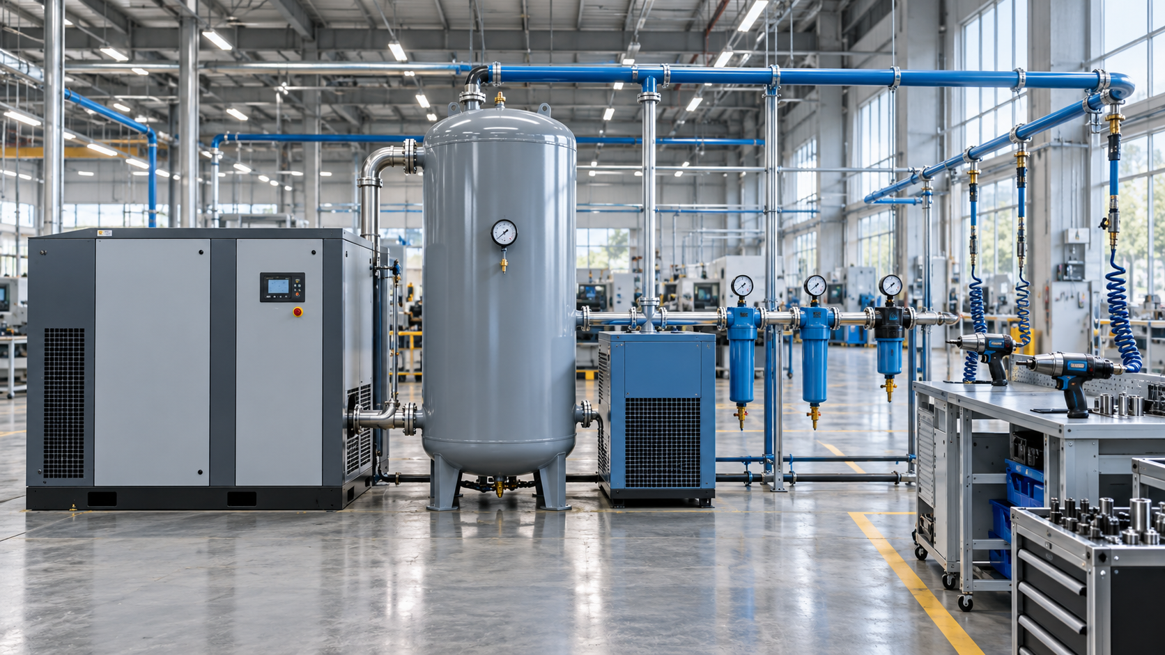
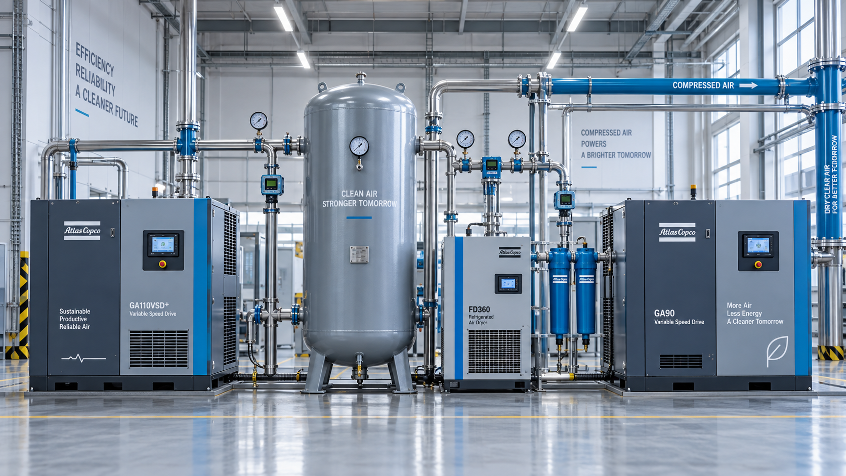
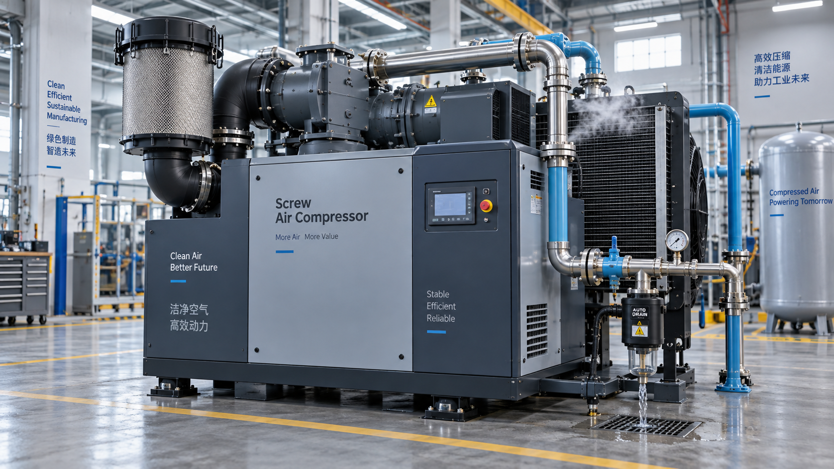
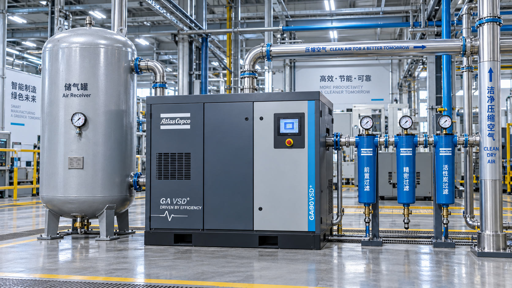
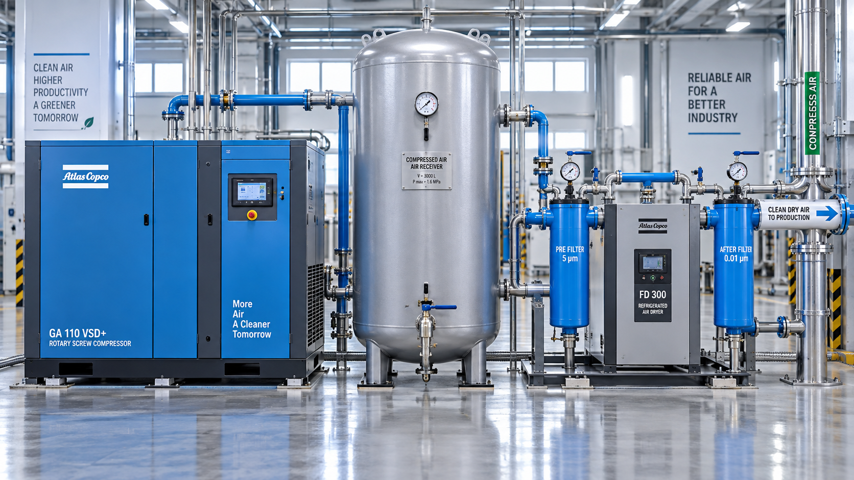
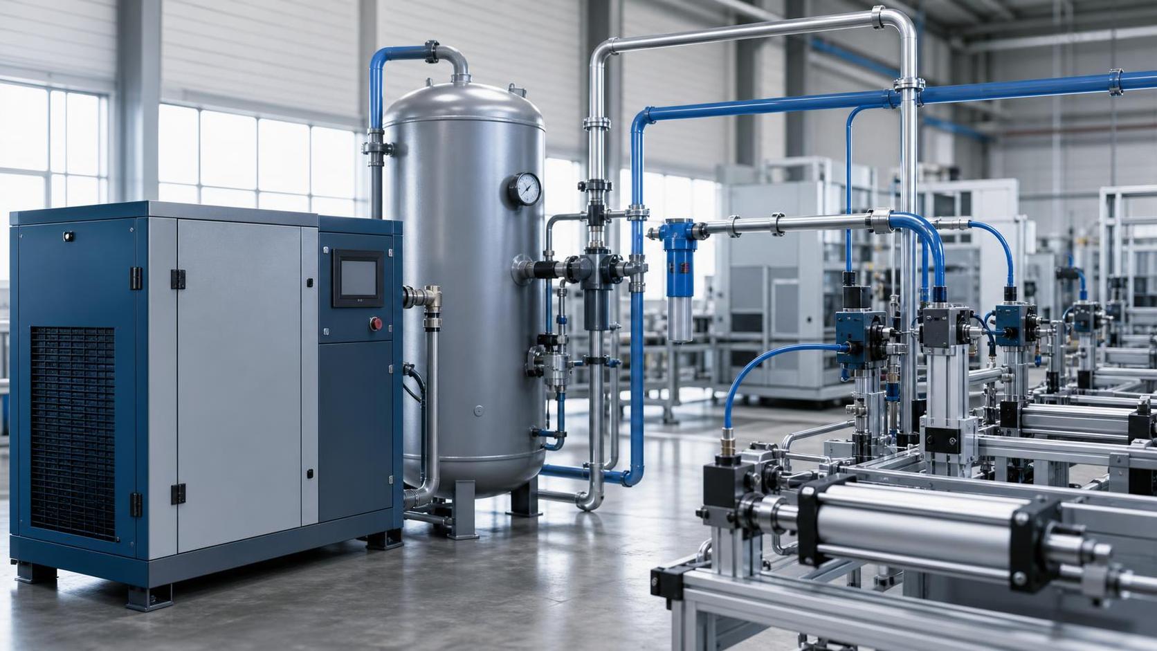
For technical evaluators, the goal is to establish a stable supply of usable air at the point of use: enough flow, at the required pressure, with the required air quality, through the actual operating cycle. The compressor is only one element. Receivers, dryers, filters, piping, controls, drainage, and allowances for change all determine whether compressed air equipment for pneumatic tools will support production without excessive energy use or recurring troubleshooting.
The most reliable approach begins with demand at the tool, then works backward through the distribution system to the compressor room. That sequence prevents a common and expensive mistake: selecting a larger compressor to compensate for pressure loss, leakage, poor storage design, or an undersized air treatment train.
Start with the actual tool demand, not the nameplate alone
Tool catalogues commonly state air consumption in L/min, cfm, scfm, or sometimes in a way that does not clearly distinguish free-air delivery from compressed volume at line pressure. Before combining values, confirm the manufacturer’s reference conditions and the operating pressure used for the published rating. A value measured at one pressure cannot be treated as directly equivalent to a value measured under another set of conditions.
Also distinguish between a tool’s average consumption and its instantaneous demand. A die grinder used continuously can create a relatively steady load. An impact wrench consumes air in bursts. A blow gun, pneumatic cylinder bank, or air knife can generate brief but substantial peaks. If a sizing exercise simply adds every maximum catalogue flow figure, the result can be needlessly oversized. If it uses only average consumption without considering peak events, the system may be unstable.
Build a demand schedule for each relevant point of use. It should record the tool type, minimum inlet pressure, stated consumption, expected duty cycle, number installed, number likely to operate simultaneously, and whether operation is continuous, intermittent, or peak-driven. For an existing facility, field measurement is often more useful than assumptions. Logging compressor output, receiver pressure, and demand over representative shifts can reveal patterns that a tool list will miss.
A practical way to calculate the baseline
For each group of similar tools, estimate the expected free-air demand using:
Expected demand = stated tool air consumption × number operating simultaneously × duty cycle
Add the expected demand of each group, then include known process loads such as pneumatic actuators, parts blow-off, instrument air, packaging equipment, or occasional cleaning stations. This result is a starting point rather than a final compressor rating. The next step is to examine the shape of demand. A plant whose load is steady at most hours needs a different compressor and receiver strategy from one where several tools fire at the same time for a few seconds every minute.
Avoid adding an arbitrary “safety factor” before understanding the system. Some capacity reserve is sensible for uncertainty, leakage, degradation, maintenance coverage, and planned expansion. But a vague margin can conceal poor demand data. It is better to identify the reason for each allowance: anticipated new stations, seasonal ambient effects, a known leakage condition pending repair, or the need to retain capacity while one compressor is serviced.
Pressure at the tool is the sizing constraint that often gets missed
Pneumatic tools are rated for an inlet pressure, not merely for a compressor discharge pressure. If an impact wrench requires a specified inlet pressure to achieve its stated fastening performance, the relevant question is whether that pressure exists at the wrench while it is operating. Pressure measured beside the compressor may look healthy while the far end of the plant experiences a meaningful drop.
Pressure loss accumulates through undersized mains, long flexible hoses, restrictive couplings, quick-connect fittings, filters, regulators, dryers, separators, and partially closed valves. Contamination and poor maintenance increase that loss over time. In practice, a regulator selected too close to its flow limit can be just as disruptive as a small pipe. The tool may then be blamed for poor output even though the restriction lies upstream.
Set the required system pressure by working backward from the most demanding point of use. Establish the minimum pressure required at that point during load, then account for the expected pressure drop across local treatment, distribution piping, and the compressor-side equipment. Raising compressor set pressure should be a last response, not the default remedy. It increases the energy burden and may intensify leakage, while leaving the original restriction in place.
Match the compressor to the demand profile
The compressor selection should be based on its verified free air delivery at the intended operating pressure, not solely on nominal horsepower, displacement, or a broad marketing capacity range. Two machines with similar motor sizes may provide different usable output once pressure, ambient conditions, control strategy, and package configuration are considered.
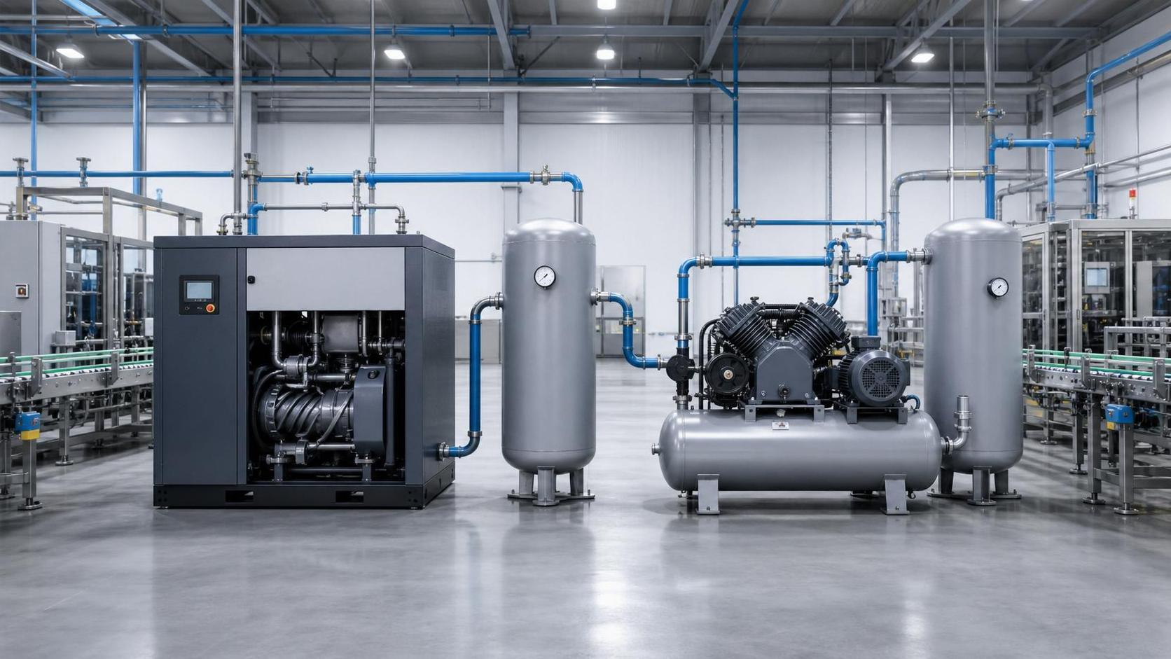
For a relatively small, intermittent tool load, a fixed-speed compressor with adequate storage may be appropriate where simplicity matters and operating hours are limited. For a demand profile that varies significantly through the day, a variable-speed compressor can reduce unloaded operation when it is properly matched to the system’s turndown range. It is not automatically the right answer. A variable-speed unit that remains near full load most of the time may offer limited control-related benefit, while a poorly sized system can still short-cycle or run inefficiently.
Larger installations often benefit from a combination of compressors rather than one oversized machine. A smaller trim unit may cover low-demand periods while a base-load machine carries predictable demand. The best arrangement depends on load variation, redundancy expectations, maintenance practices, electricity tariff structure, and how critical pneumatic tools are to production. Critical assembly or safety-related operations may justify a different resilience decision from a non-critical workshop utility load.
Storage is not a substitute for capacity, but it changes system behavior
Air receivers store compressed air and reduce the severity of short peaks. They can stabilize pressure, reduce rapid compressor cycling, provide time for control response, and help separate condensate when installed in an appropriate location. They are particularly useful where tools consume air in bursts, but they cannot correct a sustained deficit between compressor output and plant demand.
Receiver sizing should be linked to the allowable pressure band and the duration of the peak event. A wide pressure swing may allow more stored energy, but only if the tools and process can tolerate the lower end of that band. If the point-of-use requirement is tight, the usable storage volume can be much less than expected. Separate wet and dry receivers may be considered depending on the treatment arrangement and the operational objective.
For tool-heavy areas located far from the compressor room, local storage can sometimes improve transient response. It must be paired with appropriately sized piping and proper condensate management. Adding a receiver to a restricted branch line does not remove the restriction; it only delays the moment when pressure loss becomes visible.
Treat air quality as part of the equipment size
Pneumatic tools vary widely in their tolerance for water, oil aerosol, particles, and dry air. General workshop tools may require lubrication or have relatively modest purity needs. Paint application, food handling, pharmaceutical operations, electronics work, instrumentation, and sensitive assembly environments may require much tighter control. There is no universal filter-and-dryer package that suits every application.
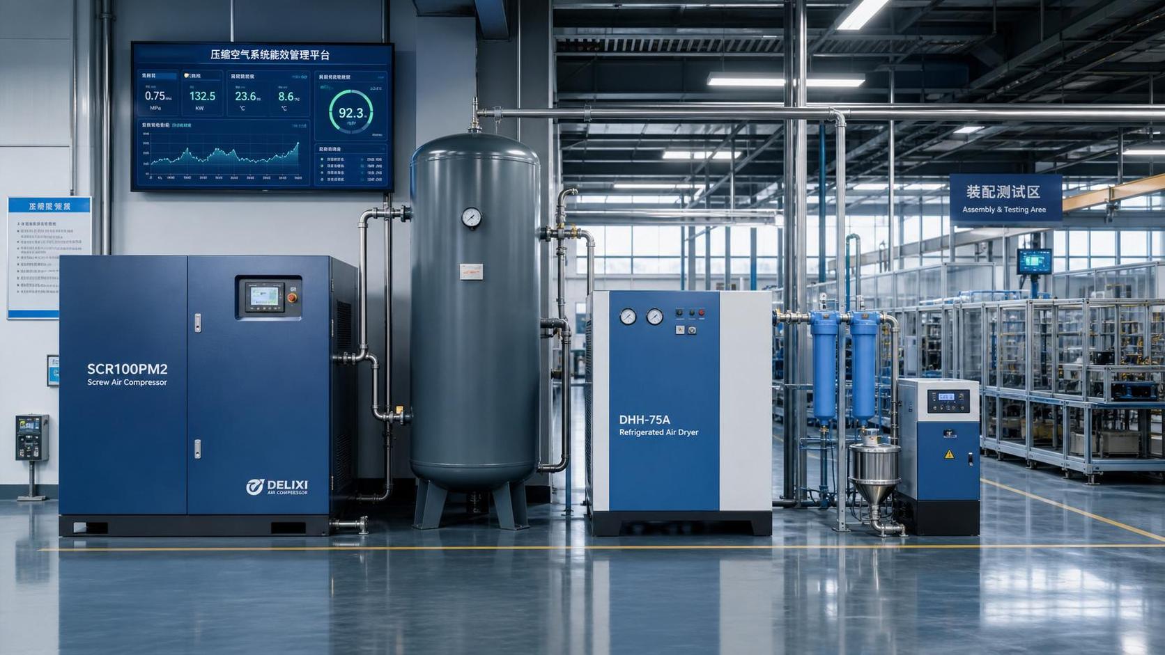
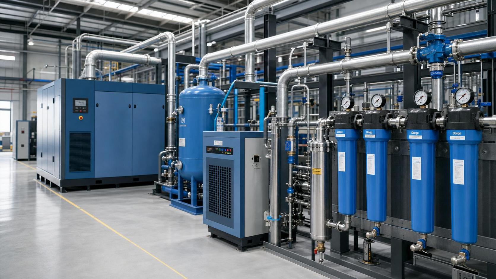
The treatment train must be sized for actual flow and selected for the required outlet condition at the site’s operating temperature and pressure. Refrigerated dryers, desiccant dryers, coalescing filters, particulate filters, drains, and oil-removal measures each have a distinct purpose. A dryer can be technically correct yet undersized for peak flow. A fine filter can protect a process but impose unacceptable pressure loss if its flow capacity, differential-pressure condition, or maintenance interval is ignored.
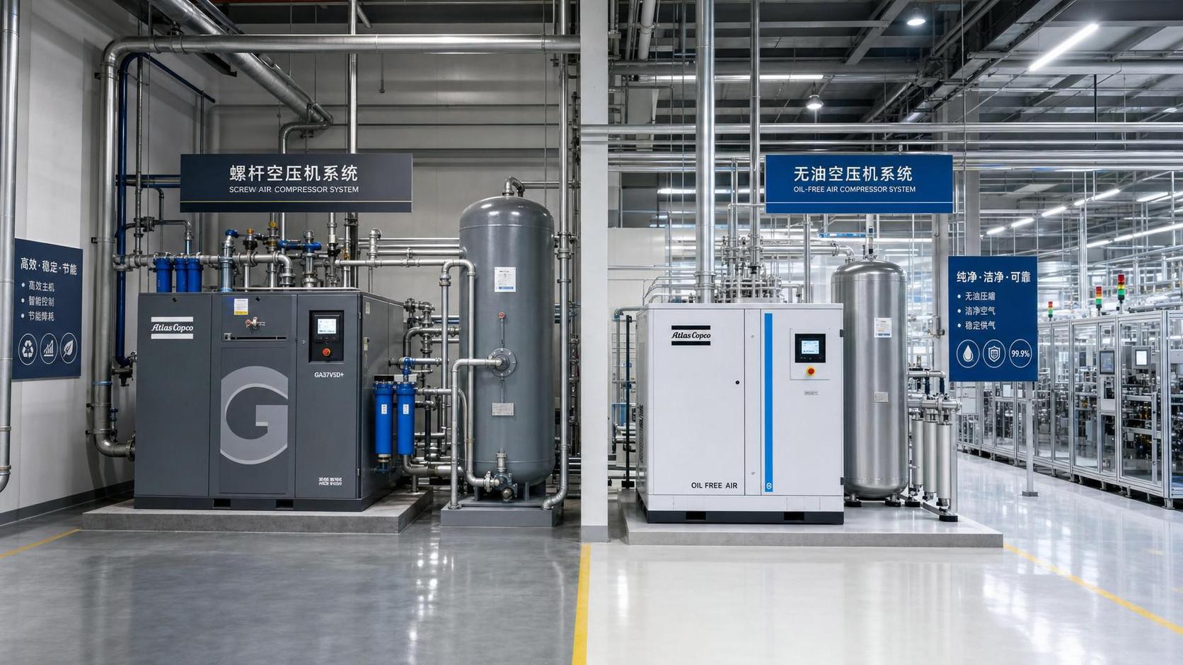
For oil-sensitive applications, the decision is broader than choosing an oil-free compressor or an oil-lubricated compressor. The complete risk path matters: intake conditions, compression technology, downstream treatment, piping cleanliness, maintenance procedures, and verification requirements. Specific purity classes and test methods should be confirmed against the customer’s process specifications and applicable standards rather than assumed from the compressor type alone.
Distribution design can preserve—or waste—the capacity you buy
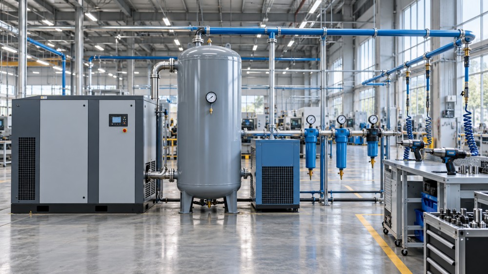
A well-sized compressor cannot overcome a poorly designed network indefinitely. Main headers should be sized around expected flow, route length, future branches, and acceptable pressure drop. Ring mains can offer more than one path to a demand area and may improve pressure stability compared with a long dead-end run. Branches should be arranged to limit water carryover, and low points need drainage provisions. Flexible hoses should be kept as short and appropriately sized as practical.
Leakage deserves separate attention. It is easy to include leakage as a permanent capacity allowance and move on, but that approach turns waste into a design requirement. A leak survey during non-production hours can distinguish genuine tool demand from avoidable base load. Pressure and flow logging before final procurement can also expose demand that only occurs during shift changes, cleaning routines, or automated cycle transitions.
A decision checklist before releasing the specification
- Confirm each critical tool’s minimum inlet pressure and air-consumption reference condition.
- Identify simultaneous use and peak events instead of counting installed tools alone.
- Calculate expected pressure loss through treatment, piping, fittings, hoses, and regulators.
- Specify compressor free air delivery at the operating pressure and expected ambient conditions.
- Determine receiver volume from peak duration and acceptable pressure swing.
- Define air-quality requirements at the point of use, including water, particulate, and oil concerns.
- Document expansion, maintenance coverage, electrical constraints, noise limits, drainage, and monitoring needs.
The final specification should state the duty clearly enough that suppliers are quoting against the same basis. “Compressor for ten pneumatic tools” is not a usable technical brief. A credible brief describes required delivered flow, pressure at the critical point of use, load profile, air quality, utility conditions, operating schedule, and constraints around installation and maintenance.
This systems view aligns with the work followed by GTC-Matrix across compressed air, industrial cooling, vacuum processes, and heat-exchange technologies. Its Strategic Intelligence Center examines energy conversion as an interconnected operating system: thermodynamic performance, pneumatic power demand, operating economics, and changing requirements in sectors such as food, pharmaceuticals, and semiconductor manufacturing. For compressed air decisions, that perspective is useful because the lowest-risk choice is rarely found in a compressor datasheet alone.
Before committing to compressed air equipment for pneumatic tools, validate the demand profile with production, maintenance, and process teams. Then test the proposed configuration against the worst credible combination of flow, pressure, air quality, and operating conditions. A system that meets those conditions with measured reserve is more likely to deliver consistent tool performance without carrying unnecessary energy and maintenance cost for years afterward.
Related News
- How to size compressed air equipment for pneumatic toolsAuthor :Pneumatic Power Engineer

- How Should Energy Management Systems Handle Compressor Load Changes?Author :Pneumatic Power Engineer

- Which Maintenance Issues Reduce Air Compressor Efficiency?Author :Pneumatic Power Engineer

- How Much Energy Can Variable-Speed Screw Compressors Save?Author :Pneumatic Power Engineer

- Industrial Compressor Selection: Matching Flow, Pressure, and Duty CycleAuthor :Pneumatic Power Engineer

- China Expands Cross-Border RMB and FX Cash Pooling NationwideAuthor :Pneumatic Power Engineer

- How to Size Air Compressor Systems for Pneumatics by Flow and Pressure DemandAuthor :Pneumatic Power Engineer

- How Energy Recovery Systems for Compressors Cut Power CostsAuthor :Pneumatic Power Engineer

- How to Evaluate Screw Compressors in Industrial Refrigeration EquipmentAuthor :Pneumatic Power Engineer

- India Makes BIS Certification Mandatory for Screw CompressorsAuthor :Pneumatic Power Engineer

- China Tightens Export Filing for Screw CompressorsAuthor :Pneumatic Power Engineer

- SABIC Sets IoT Interface Rule for Screw CompressorsAuthor :Pneumatic Power Engineer

- Industrial Heat Recovery Systems for Compressors: When Do Energy Savings Pay Back?Author :Pneumatic Power Engineer

- EU Tightens REACH Limit for Screw Compressor LubricantsAuthor :Pneumatic Power Engineer

- EU Opens China Screw Compressor Review With Carbon RuleAuthor :Pneumatic Power Engineer

- DOE Mandates AHRI 1000-2026 for Screw CompressorsAuthor :Pneumatic Power Engineer

- VDMA Filing Signals EU Risk for Chinese Oil Screw CompressorsAuthor :Pneumatic Power Engineer
![]()
- Screw vs Piston Air Compressors for Stable Plant OutputAuthor :Pneumatic Power Engineer

- Saudi SASO Tightens Refrigerant Limits in IEC 60335-2-40:2026Author :Pneumatic Power Engineer

- IIR Warns of 18-Week Lead Times for Screw CompressorsAuthor :Pneumatic Power Engineer

- Welded Compressed Air Manifold Selection Guide for Pressure Stability and LeaksAuthor :Pneumatic Power Engineer

- India BIS Rule Adds IS 16830 Requirement for Imported Screw CompressorsAuthor :Pneumatic Power Engineer

- What to Check Before Choosing a Compressed Air FactoryAuthor :Pneumatic Power Engineer

- China Tightens Export Checks on Screw CompressorsAuthor :Pneumatic Power Engineer

- Screw Compressor Lead Times Reach 22 WeeksAuthor :Pneumatic Power Engineer

- Vietnam Requires QR Labels on Imported Screw CompressorsAuthor :Pneumatic Power Engineer

- Compressed Air Technologies Filtration: How to Reduce Pressure Drop and Energy LossAuthor :Pneumatic Power Engineer

- STSPIN830 Lead Time Tops 32 Weeks in Screw CompressorsAuthor :Pneumatic Power Engineer

- IGBT Shortage Extends Screw Compressor Lead TimesAuthor :Pneumatic Power Engineer

- Compressed Air Systems: 7 Hidden Costs That Raise Total Operating ExpenseAuthor :Pneumatic Power Engineer

- Compressed Air Efficiency: 7 Hidden Losses That Raise Operating CostsAuthor :Pneumatic Power Engineer

- How to Compare Screw vs Oil-Free Air Compression SystemsAuthor :Pneumatic Power Engineer

- Compressed Air Leaks: What They Really Cost in Daily OperationsAuthor :Pneumatic Power Engineer

- DOE Moves Up R449A Chiller Deadline to March 2027Author :Pneumatic Power Engineer

- How Compression Technology Cuts Energy Use in Modern PlantsAuthor :Pneumatic Power Engineer

- EU Adds GB 18613-2025 to Import Energy ChecksAuthor :Pneumatic Power Engineer