



How to Size Air Compressor Systems for Pneumatics by Flow and Pressure Demand




Why compressor sizing for pneumatics is often wrong at the starting point
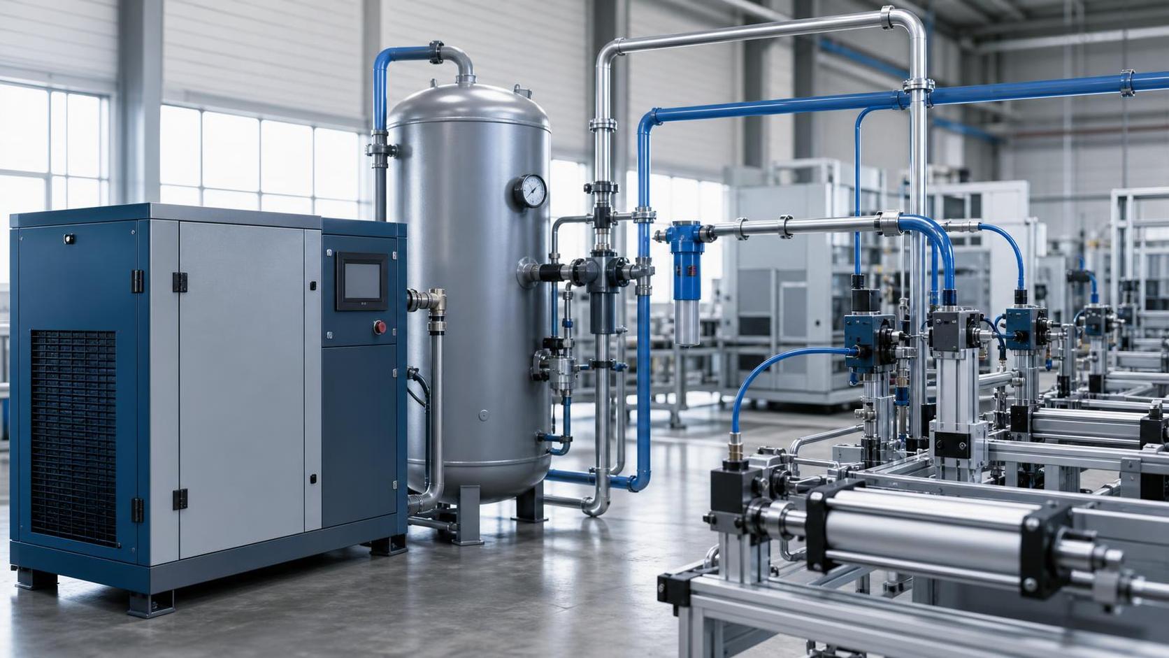
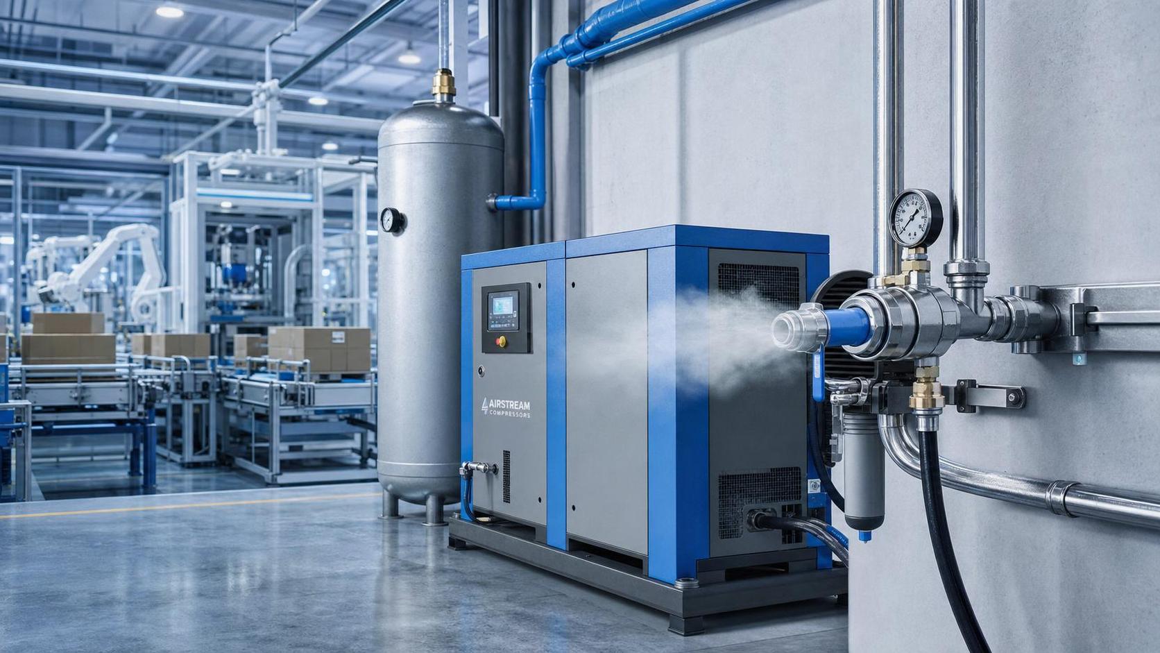
Sizing air compressor systems for pneumatics is less about choosing a machine with a comfortable nameplate margin and more about understanding how the plant actually consumes compressed air. That sounds obvious, yet many systems are still selected from a rough total of tool consumption, then padded with extra capacity "for safety." The result is familiar: unstable pressure at peak demand, compressors that run unloaded for long periods, avoidable energy cost, and production teams who assume the compressor is undersized when the real issue is how demand was characterized.
The key mistake is treating flow and pressure as independent numbers. In pneumatic systems, they are coupled through the distribution network, storage volume, control method, and the way end uses cycle. A line may appear to need a certain free air delivery because several actuators can run at once, but if those actuators are short-stroke, intermittent, and sequenced, the demand profile looks very different from a process with continuous blow-off nozzles or air knives. Pressure behaves the same way. The number specified at the compressor discharge is not the number that matters if the point of use sees a lower value after filtration, dryers, regulators, and piping losses.
For technical evaluation work, the practical question is not simply, "How large should the compressor be?" It is, "What combination of compressor capacity, control range, storage, and pressure architecture will support the real pneumatic load with acceptable stability and energy behavior?" That is the level where equipment decisions become defensible.
Start from demand at the point of use, not from compressor catalog ratings
When engineers discuss air compressor systems for pneumatics, the useful reference point is the air requirement at the application, usually expressed as pressure needed at the end device and air consumption over time. Compressor catalogs, by contrast, present machine performance under defined conditions, often as FAD, or free air delivery. Those figures matter, but they only become meaningful after the plant demand has been translated into a compatible basis.
That translation is where many evaluations go off course. Pneumatic cylinders, grippers, ejectors, air bearings, purge functions, and blow molding auxiliaries do not consume air in the same way. Some loads are nearly continuous. Others create very sharp transient peaks. A system can have a low average flow and still need a surprisingly robust compressor arrangement because the short-term demand spikes exceed what the control system and receiver can absorb without pressure sag.
A useful working distinction is this:
- Average demand determines much of the long-run energy profile.
- Peak demand determines whether pressure remains usable during the critical moments of operation.
- Minimum required pressure at the end use determines the lower limit of acceptable system performance.
If one of those three is missing from the evaluation, the sizing exercise is incomplete.
Flow is not a single number in real pneumatic production
In many plants, the stated flow requirement is really a mixed estimate: nameplate consumption from some devices, rule-of-thumb additions for leaks, and a general contingency factor. That may be enough for a first conversation, but it is not enough for a decision. Pneumatic demand should be separated into at least three layers: base load, intermittent process load, and abnormal or maintenance-related consumption.
Base load covers the air that is drawn almost continuously, including instruments, steady air bearings, permanent purge points, and unavoidable background leakage. Intermittent process load includes actuators and air-driven functions tied to machine cycles, product changeovers, or batch operations. Abnormal consumption includes manual blow-offs left open, temporary tools, drain malfunctions, and leak growth that develops over time. The third category is uncomfortable because it reflects poor operating discipline, but excluding it entirely can produce unrealistic sizing, especially in older factories.
The goal is not to normalize waste into the design forever. It is to distinguish between air that should be designed for and air that should be eliminated through maintenance, controls, or network remediation. That distinction affects whether the right answer is a bigger compressor, a larger receiver, a lower pressure drop network, or a leak reduction program.
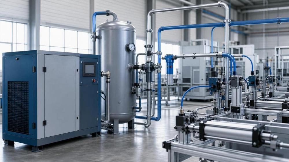
Pressure demand is usually misread because losses are distributed across the system
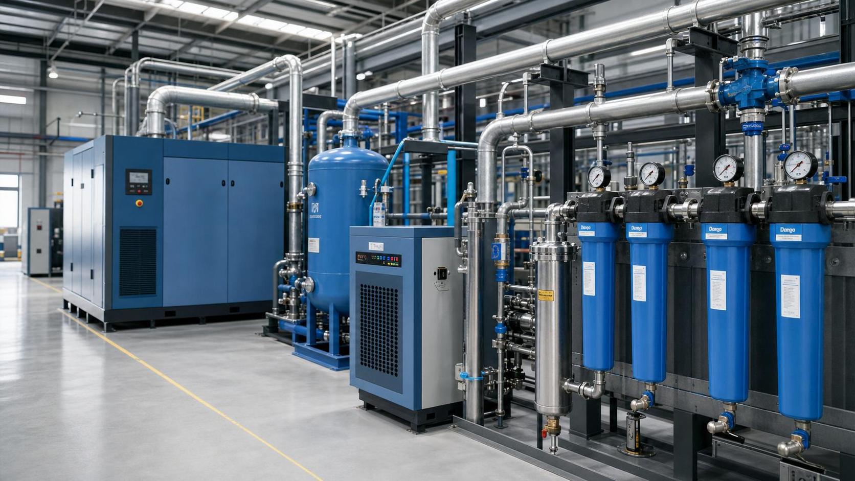
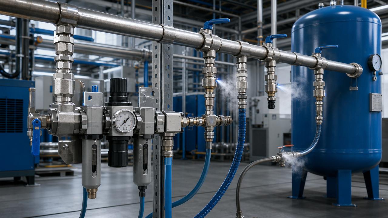
Pressure selection gets distorted when teams focus on the highest number they can find in the process and then impose that value on the whole compressed air system. In practice, what matters is the minimum pressure needed at each critical point of use, plus the pressure losses between the compressor room and those points. Those losses can come from undersized piping, long branches, poorly selected filters, contaminated separators, dryers approaching service limits, or regulators set too conservatively.
That is why a compressor discharge setpoint should not be chosen as a blanket insurance policy. Raising system pressure to cover one difficult branch often increases energy consumption across the entire network and can make leakage worse. In some applications, it also causes pneumatic components to operate more aggressively than necessary, accelerating wear or making machine motion harder to control.
A more disciplined approach is to map the pressure chain backward. Start with the most pressure-sensitive end use. Add realistic losses for treatment equipment, regulators, and distribution. Then examine whether those losses are intrinsic or avoidable. If they are avoidable, fixing them may be more rational than specifying a larger compressor or a higher plant header pressure.
The receiver and control method can change the answer materially
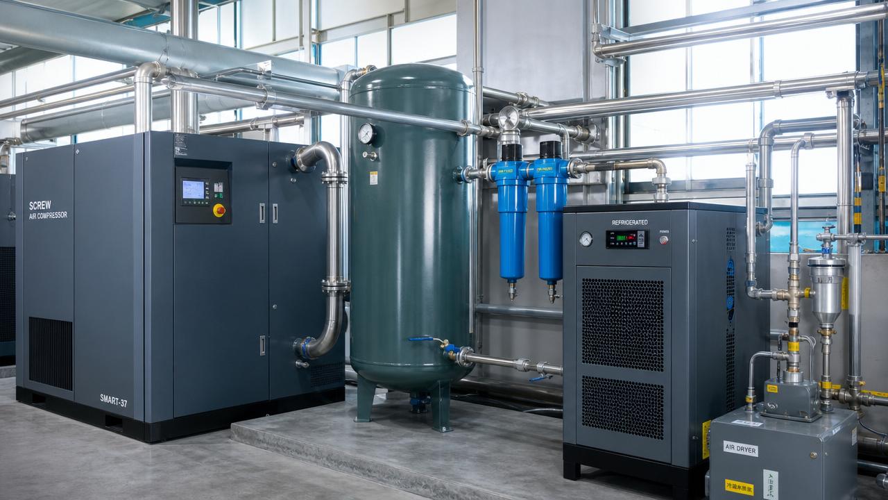
Compressor sizing for pneumatics is often discussed as though the compressor alone carries the full burden of every fluctuation. That is not how a well-behaved system works. Air receivers, local storage near fast-cycling loads, and the compressor control strategy all influence what installed compressor capacity is actually required.
A receiver does not create air, but it can buffer short events that would otherwise force the compressor into unstable cycling or drive a pressure drop at the header. This matters in plants where several pneumatic machines start nearly together, or where one process creates brief but repeated surges. In such cases, storage may reduce the need to size the compressor purely for transient peaks.
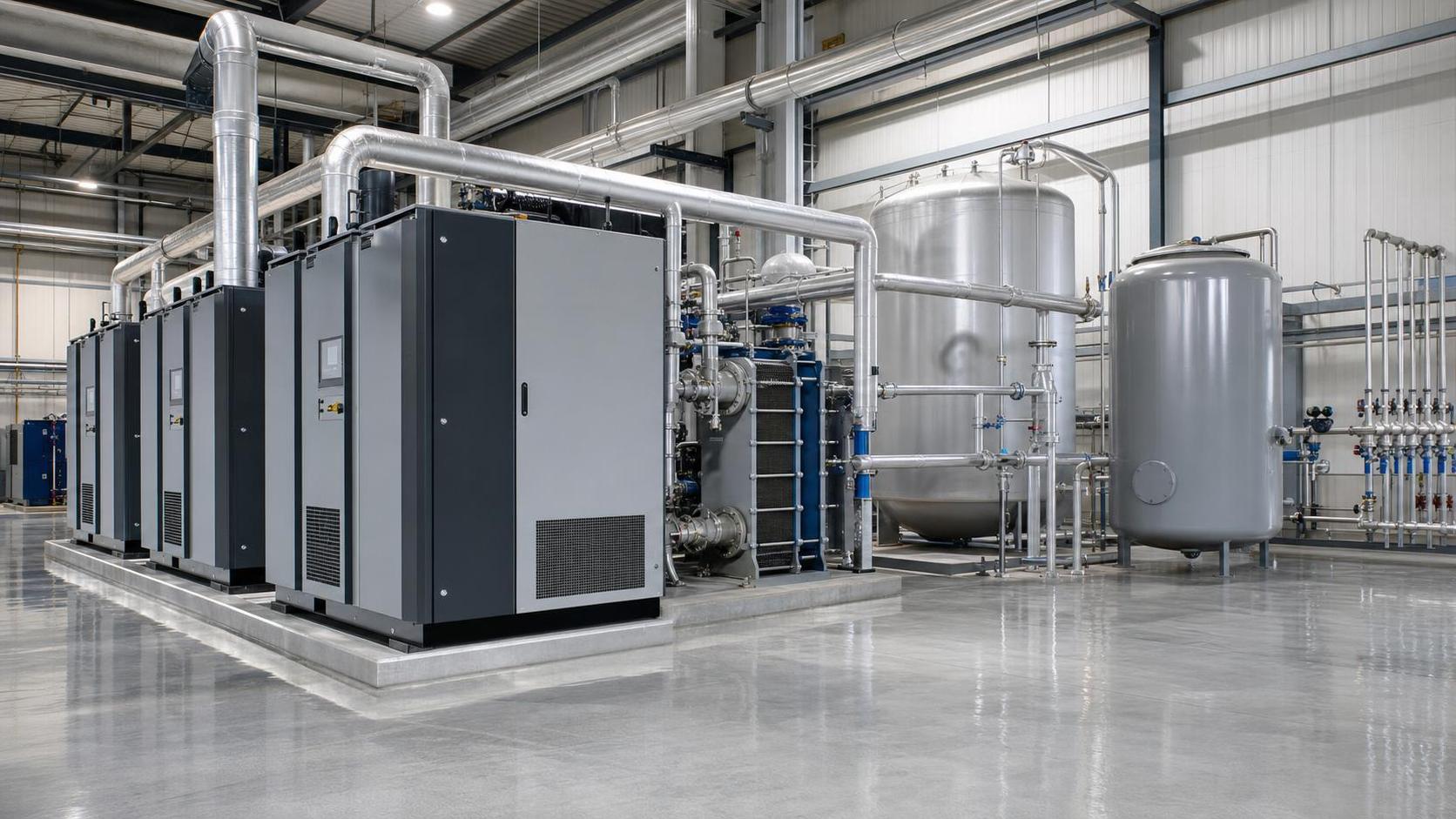
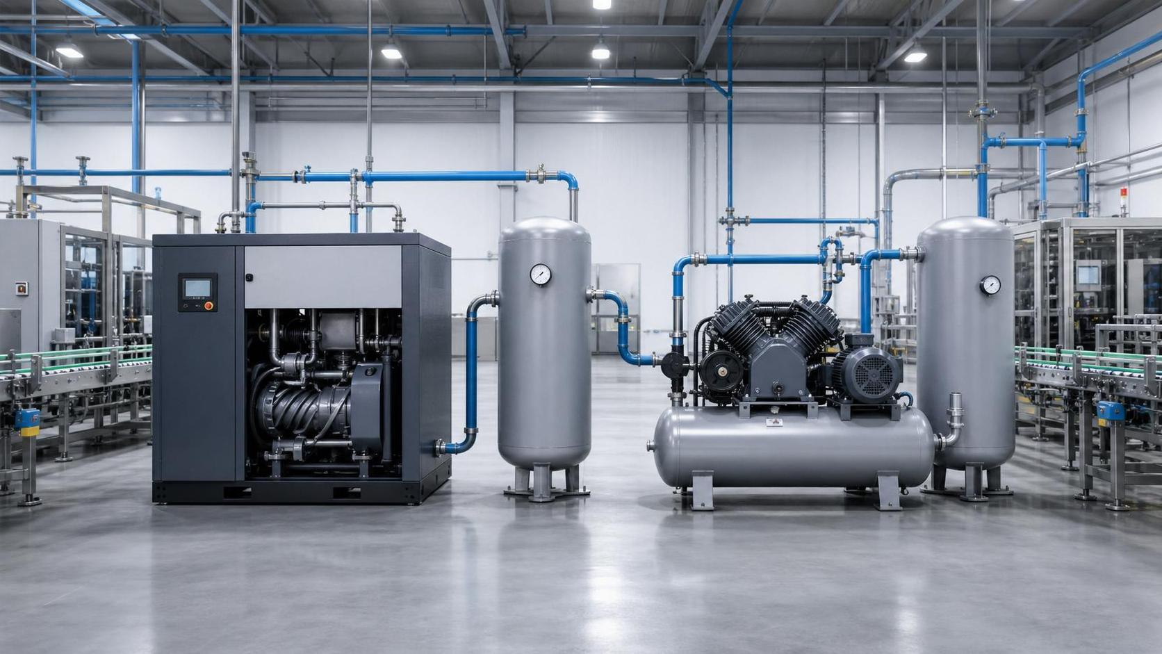
Control philosophy matters just as much. Fixed-speed compressors with load-unload control behave differently from variable-speed machines. Multi-compressor installations add another layer, because staging logic determines whether the system tracks demand smoothly or spends too much time in inefficient operating zones. A technical evaluator should be cautious about accepting a capacity figure without knowing how that capacity will be controlled in the expected load range. A nominally adequate machine can perform poorly if the turn-down behavior is mismatched to plant demand variability.
A practical evaluation framework
For selection work, a structured but not overly theoretical sequence is usually enough:
This framework is deliberately simple. It reflects how many real projects are judged: not by perfectly complete data, but by whether the assumptions are explicit, the weak points are visible, and the sizing logic can survive challenge from operations, maintenance, and energy management teams.
Common misunderstandings that distort compressor selection
One common misunderstanding is that more pressure solves a flow problem. It can conceal the symptom for a while, especially if receivers are small or controls are slow, but it often shifts cost elsewhere. Another is that leak rate should simply be added to compressor capacity and forgotten. In a mature evaluation, leakage is a condition to be measured and managed, not just a permanent design allowance.
There is also a tendency to size around simultaneous maximum consumption of every pneumatic device. That can be reasonable in a tightly synchronized process, but in many production systems it exaggerates the requirement because not all loads overlap in time. The opposite mistake exists as well: averaging everything over a shift and ignoring machine-level surges. Both errors come from compressing demand behavior into one number.
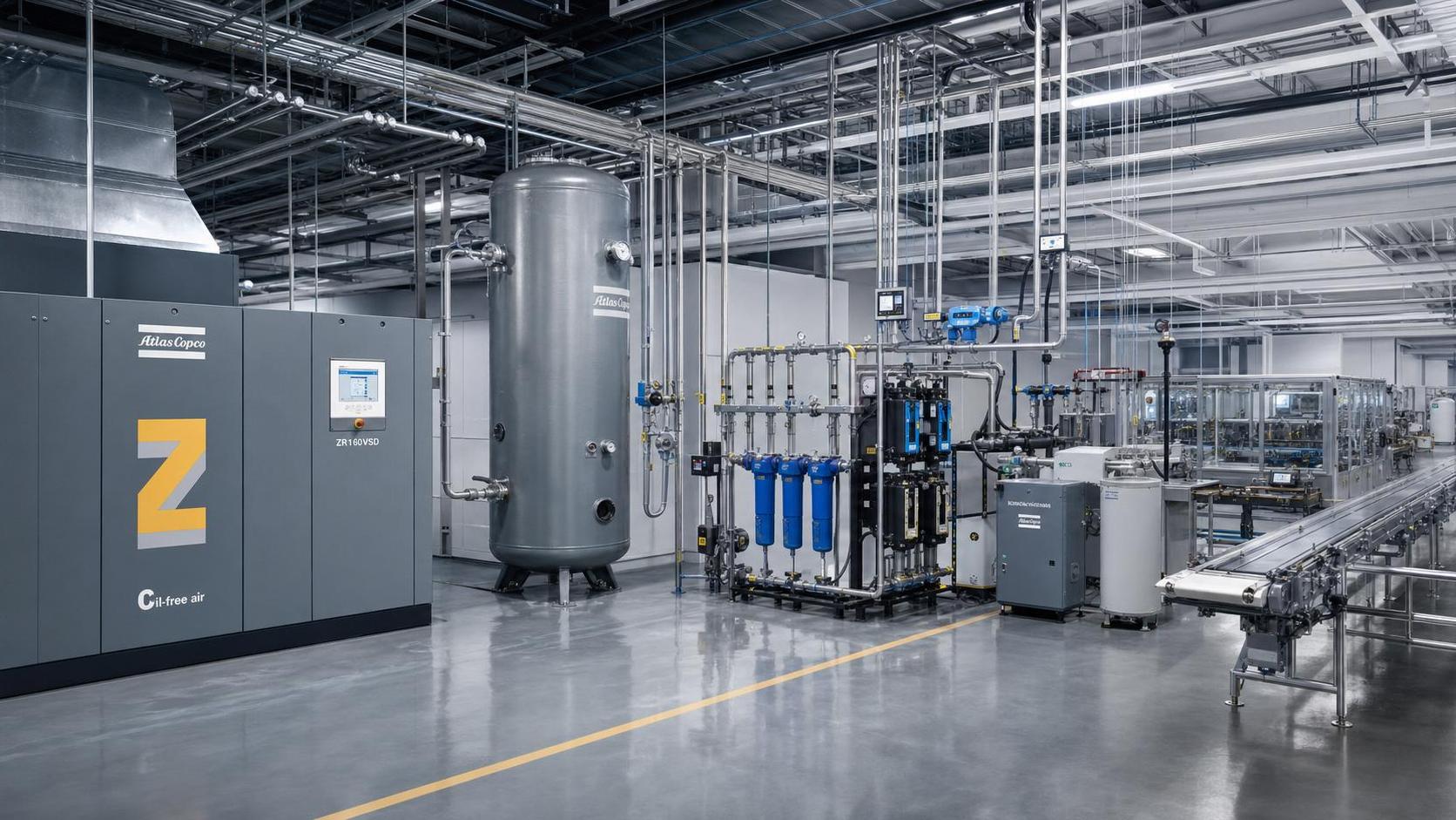
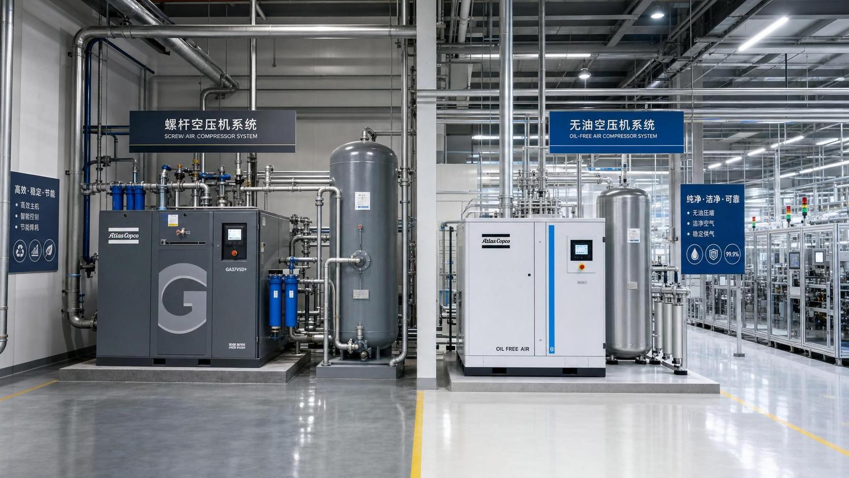
Oil-free versus lubricated compression can enter the discussion too, although it is not a sizing parameter by itself. It becomes relevant when air quality requirements in food, pharmaceutical, electronics, or sensitive process applications constrain the compressor technology and treatment train. In those cases, the selected architecture may influence pressure drop, control strategy, and lifecycle cost, which then loops back into the sizing decision.
What a defensible sizing decision looks like
A defensible decision on air compressor systems for pneumatics does not pretend the future is fully known. It shows that the current load was characterized in terms of actual flow pattern and required pressure at the end use; that treatment and distribution losses were considered; that storage and control behavior were not ignored; and that future expansion was handled with a reasoned margin rather than a vague safety factor.
For technical evaluators, that is usually the dividing line between a compressor system that merely runs and one that remains stable, efficient, and explainable over time. If the proposed capacity cannot be traced back to real demand behavior, pressure architecture, and control assumptions, the number may still be workable, but it is not yet well sized. In pneumatic systems, that distinction matters more than the catalog headline.
Related News
- China Expands Cross-Border RMB and FX Cash Pooling NationwideAuthor :Pneumatic Power Engineer

- How to Size Air Compressor Systems for Pneumatics by Flow and Pressure DemandAuthor :Pneumatic Power Engineer

- How Energy Recovery Systems for Compressors Cut Power CostsAuthor :Pneumatic Power Engineer

- How to Evaluate Screw Compressors in Industrial Refrigeration EquipmentAuthor :Pneumatic Power Engineer

- India Makes BIS Certification Mandatory for Screw CompressorsAuthor :Pneumatic Power Engineer

- China Tightens Export Filing for Screw CompressorsAuthor :Pneumatic Power Engineer

- SABIC Sets IoT Interface Rule for Screw CompressorsAuthor :Pneumatic Power Engineer

- Industrial Heat Recovery Systems for Compressors: When Do Energy Savings Pay Back?Author :Pneumatic Power Engineer

- EU Tightens REACH Limit for Screw Compressor LubricantsAuthor :Pneumatic Power Engineer

- EU Opens China Screw Compressor Review With Carbon RuleAuthor :Pneumatic Power Engineer

- DOE Mandates AHRI 1000-2026 for Screw CompressorsAuthor :Pneumatic Power Engineer

- VDMA Filing Signals EU Risk for Chinese Oil Screw CompressorsAuthor :Pneumatic Power Engineer
![]()
- Screw vs Piston Air Compressors for Stable Plant OutputAuthor :Pneumatic Power Engineer

- Saudi SASO Tightens Refrigerant Limits in IEC 60335-2-40:2026Author :Pneumatic Power Engineer

- IIR Warns of 18-Week Lead Times for Screw CompressorsAuthor :Pneumatic Power Engineer

- Welded Compressed Air Manifold Selection Guide for Pressure Stability and LeaksAuthor :Pneumatic Power Engineer

- India BIS Rule Adds IS 16830 Requirement for Imported Screw CompressorsAuthor :Pneumatic Power Engineer

- What to Check Before Choosing a Compressed Air FactoryAuthor :Pneumatic Power Engineer

- China Tightens Export Checks on Screw CompressorsAuthor :Pneumatic Power Engineer

- Screw Compressor Lead Times Reach 22 WeeksAuthor :Pneumatic Power Engineer

- Vietnam Requires QR Labels on Imported Screw CompressorsAuthor :Pneumatic Power Engineer

- Compressed Air Technologies Filtration: How to Reduce Pressure Drop and Energy LossAuthor :Pneumatic Power Engineer

- STSPIN830 Lead Time Tops 32 Weeks in Screw CompressorsAuthor :Pneumatic Power Engineer

- IGBT Shortage Extends Screw Compressor Lead TimesAuthor :Pneumatic Power Engineer

- Compressed Air Systems: 7 Hidden Costs That Raise Total Operating ExpenseAuthor :Pneumatic Power Engineer

- Compressed Air Efficiency: 7 Hidden Losses That Raise Operating CostsAuthor :Pneumatic Power Engineer

- How to Compare Screw vs Oil-Free Air Compression SystemsAuthor :Pneumatic Power Engineer

- Compressed Air Leaks: What They Really Cost in Daily OperationsAuthor :Pneumatic Power Engineer

- DOE Moves Up R449A Chiller Deadline to March 2027Author :Pneumatic Power Engineer

- How Compression Technology Cuts Energy Use in Modern PlantsAuthor :Pneumatic Power Engineer

- EU Adds GB 18613-2025 to Import Energy ChecksAuthor :Pneumatic Power Engineer

- EU CE Rule Adds SRA for R290 Compressor ImportsAuthor :Pneumatic Power Engineer

- Compressed Air Leaks: Hidden Costs and Practical Ways to Reduce LossesAuthor :Pneumatic Power Engineer

- Kunming Sourcing Festival Adds Thermal & Compression HubAuthor :Pneumatic Power Engineer

- Compressed Air Efficiency: Where Energy Losses Usually StartAuthor :Pneumatic Power Engineer

- US 3-Year Treasury Yield Rise Pressures Compressor Export QuotesAuthor :Pneumatic Power Engineer