Welded Compressed Air Manifold Selection Guide for Pressure Stability and Leaks




Welded Compressed Air Manifold Selection Guide for Pressure Stability and Leaks
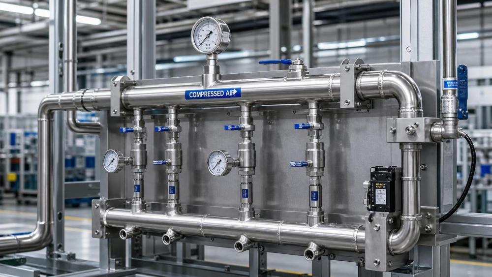
For industrial air systems, manifold selection affects far more than pipe routing. It shapes pressure balance, leak performance, maintenance workload, and long-term energy cost.
A welded compressed air manifold is often chosen for higher integrity and cleaner flow paths. That matters when uptime targets are tight and pressure variation must stay controlled.
In practice, many pressure problems do not start at the compressor. They begin at distribution points where poor manifold design creates imbalance, dead legs, or hidden leakage paths.
This guide focuses on how to select a welded compressed air manifold for stable delivery, lower leakage risk, and predictable operation in demanding production environments.
Why the Welded Compressed Air Manifold Matters
A manifold is the point where flow is divided, combined, isolated, or expanded. Its geometry directly affects pressure drop, turbulence, condensate behavior, and service accessibility.
Compared with assembled threaded headers, a welded compressed air manifold usually offers fewer leak interfaces. Fewer joints generally mean better sealing reliability over time.
That said, welding alone does not guarantee performance. A badly sized or poorly fabricated manifold can still create unstable branch pressure and difficult maintenance conditions.
The decision should therefore combine flow analysis, material fit, fabrication quality, and installation context. This is where many compressed air projects either gain resilience or inherit future problems.
Define the Real Operating Load First
Start with the actual load profile, not only the nameplate compressor capacity. The welded compressed air manifold must support peak demand, average demand, and future expansion.
Look at simultaneous tool use, machine cycle timing, pressure-sensitive equipment, and buffer tank behavior. These details reveal whether the manifold needs balanced outlets or staged supply logic.
It also helps to map critical versus noncritical branches. If one production line cannot tolerate pressure dips, the manifold design should reflect that priority clearly.
A practical review should include:
- Peak flow rate and diversity factor
- Required pressure at each branch connection
- Allowable pressure drop across the manifold
- Expected future outlet additions
- Moisture, oil, and particulate conditions
When this step is skipped, the welded compressed air manifold may look acceptable on paper but behave poorly once line demand becomes dynamic.
Size for Pressure Stability, Not Just Connection Count
Pressure stability depends heavily on internal velocity. If the header is undersized, flow accelerates, local losses rise, and downstream users see unstable air delivery.
A welded compressed air manifold should be sized around design flow, acceptable pressure drop, and branch distribution pattern. Connection quantity is only one part of the decision.
Straight-through flow paths usually perform better than abrupt turns. Branch spacing also matters. Closely clustered takeoffs can create uneven draw and branch-to-branch competition.
In many retrofit projects, a slightly larger manifold body reduces long-term operating risk more effectively than pushing the smallest possible footprint.
Key sizing checks include:
- Main bore diameter versus maximum combined flow
- Branch port diameter versus local device demand
- Distance between inlet and final outlet
- Allowance for filtration, regulators, or isolation valves
From a system view, stable pressure is usually cheaper than oversized compressor correction. Distribution efficiency is often the faster fix.
Material Choice and Weld Quality Decide Leak Risk
Material selection should reflect air quality, ambient conditions, corrosion risk, and maintenance expectations. Carbon steel may work well in controlled settings, but not in every plant.
Stainless steel is often preferred where moisture carryover, washdown exposure, or cleanliness standards are stricter. Aluminum appears in some systems, but welded suitability must be checked carefully.
For any welded compressed air manifold, weld integrity is central. Porosity, lack of fusion, misalignment, and poor surface finishing can all become leakage points or contamination traps.
Ask suppliers about welding procedure control, welder qualification, pressure testing, and inspection records. These details are more valuable than generic product claims.
Useful verification points are:
- Base material grade and traceability
- Weld process consistency
- Hydrostatic or pneumatic pressure test method
- Surface treatment and internal cleanliness
- Compatibility with drains, valves, and fittings
This is where a welded compressed air manifold either supports low-leak operation or becomes a hidden source of continuous energy loss.
Design Details That Improve Reliability
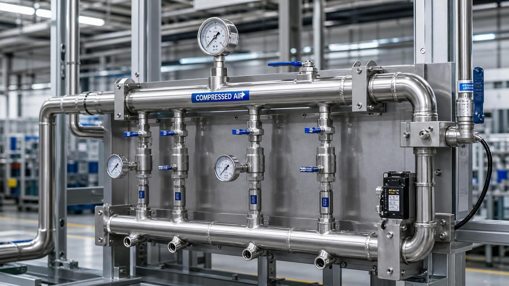
Small design details have large operating consequences. Drainage points, port orientation, and service clearance often determine whether the manifold remains stable after years of use.
A well-designed welded compressed air manifold should avoid stagnant pockets where condensate can collect. Even dry air systems benefit from planning for occasional moisture migration.
Isolation capability is another strong design choice. Branch valves make troubleshooting faster and reduce the need for full-line shutdown during maintenance.
Instrumentation ports are equally useful. Pressure gauges or transmitters at the manifold help confirm whether instability comes from supply generation or local distribution.
Consider adding these features where appropriate:
- Low-point drains
- Blanked spare outlets for expansion
- Dedicated gauge or sensor ports
- Clear branch labeling positions
- Support points that limit vibration transfer
These features keep the welded compressed air manifold practical to operate, not just compliant at installation.
Installation Conditions Often Decide Final Performance
Even a good welded compressed air manifold can underperform if installation is careless. Pipe strain, poor support, and thermal movement can distort connections and weaken sealing points.
Mount the manifold where access is realistic. If technicians cannot inspect drains, gauges, or isolation valves easily, minor issues tend to become recurring failures.
It is also wise to review upstream and downstream layout. Short-radius bends, immediate reductions, or oversized flexible hoses near the manifold can disrupt flow behavior.
Before handover, confirm leak testing under representative pressure conditions. Commissioning should include branch-by-branch verification, not only a systemwide pressure hold.
A Practical Selection Checklist
When comparing options, use a structured review. It helps separate a well-engineered welded compressed air manifold from a product that simply matches connection sizes.
In actual projects, this checklist speeds up approvals and reduces late-stage change orders. It also improves supplier discussions because the performance target becomes explicit.
Common Mistakes to Avoid
Several issues appear repeatedly in compressed air upgrades. The first is selecting a welded compressed air manifold by pipe thread count alone.
Another is ignoring future branches. A manifold with no spare capacity may force disruptive replacement long before the rest of the air system reaches end of life.
Some teams also underestimate documentation. Without test records, material details, and dimensional drawings, troubleshooting later becomes slower and more expensive.
The broader lesson is simple. A welded compressed air manifold should be evaluated as an operating asset, not a low-value accessory.
Conclusion
The right welded compressed air manifold improves pressure stability, limits leakage exposure, and supports easier maintenance across the full lifecycle of the compressed air system.
The strongest decisions come from matching load profile, sizing logic, material choice, weld quality, and installation planning. Those factors work together, and none should be treated in isolation.
For organizations tracking energy efficiency and reliability, this is also a strategic distribution decision. Better manifold design often delivers measurable value without major generation-side changes.
Use this framework to review current requirements, compare suppliers on technical evidence, and specify a welded compressed air manifold that stays stable under real operating pressure.
Ready when you are. Send us a message to get started.
Related News
- When does variable gas flow justify a custom screw compressor system?Author :Pneumatic Power Engineer

- How to size compressed air equipment for pneumatic toolsAuthor :Pneumatic Power Engineer

- How Should Energy Management Systems Handle Compressor Load Changes?Author :Pneumatic Power Engineer

- Which Maintenance Issues Reduce Air Compressor Efficiency?Author :Pneumatic Power Engineer

- How Much Energy Can Variable-Speed Screw Compressors Save?Author :Pneumatic Power Engineer

- Industrial Compressor Selection: Matching Flow, Pressure, and Duty CycleAuthor :Pneumatic Power Engineer

- China Expands Cross-Border RMB and FX Cash Pooling NationwideAuthor :Pneumatic Power Engineer

- How to Size Air Compressor Systems for Pneumatics by Flow and Pressure DemandAuthor :Pneumatic Power Engineer

- How Energy Recovery Systems for Compressors Cut Power CostsAuthor :Pneumatic Power Engineer

- How to Evaluate Screw Compressors in Industrial Refrigeration EquipmentAuthor :Pneumatic Power Engineer

- India Makes BIS Certification Mandatory for Screw CompressorsAuthor :Pneumatic Power Engineer

- China Tightens Export Filing for Screw CompressorsAuthor :Pneumatic Power Engineer

- SABIC Sets IoT Interface Rule for Screw CompressorsAuthor :Pneumatic Power Engineer

- Industrial Heat Recovery Systems for Compressors: When Do Energy Savings Pay Back?Author :Pneumatic Power Engineer

- EU Tightens REACH Limit for Screw Compressor LubricantsAuthor :Pneumatic Power Engineer

- EU Opens China Screw Compressor Review With Carbon RuleAuthor :Pneumatic Power Engineer

- DOE Mandates AHRI 1000-2026 for Screw CompressorsAuthor :Pneumatic Power Engineer

- VDMA Filing Signals EU Risk for Chinese Oil Screw CompressorsAuthor :Pneumatic Power Engineer
![]()
- Screw vs Piston Air Compressors for Stable Plant OutputAuthor :Pneumatic Power Engineer

- Saudi SASO Tightens Refrigerant Limits in IEC 60335-2-40:2026Author :Pneumatic Power Engineer

- IIR Warns of 18-Week Lead Times for Screw CompressorsAuthor :Pneumatic Power Engineer

- Welded Compressed Air Manifold Selection Guide for Pressure Stability and LeaksAuthor :Pneumatic Power Engineer

- India BIS Rule Adds IS 16830 Requirement for Imported Screw CompressorsAuthor :Pneumatic Power Engineer

- What to Check Before Choosing a Compressed Air FactoryAuthor :Pneumatic Power Engineer

- China Tightens Export Checks on Screw CompressorsAuthor :Pneumatic Power Engineer

- Screw Compressor Lead Times Reach 22 WeeksAuthor :Pneumatic Power Engineer

- Vietnam Requires QR Labels on Imported Screw CompressorsAuthor :Pneumatic Power Engineer

- Compressed Air Technologies Filtration: How to Reduce Pressure Drop and Energy LossAuthor :Pneumatic Power Engineer

- STSPIN830 Lead Time Tops 32 Weeks in Screw CompressorsAuthor :Pneumatic Power Engineer

- IGBT Shortage Extends Screw Compressor Lead TimesAuthor :Pneumatic Power Engineer

- Compressed Air Systems: 7 Hidden Costs That Raise Total Operating ExpenseAuthor :Pneumatic Power Engineer

- Compressed Air Efficiency: 7 Hidden Losses That Raise Operating CostsAuthor :Pneumatic Power Engineer

- How to Compare Screw vs Oil-Free Air Compression SystemsAuthor :Pneumatic Power Engineer

- Compressed Air Leaks: What They Really Cost in Daily OperationsAuthor :Pneumatic Power Engineer

- DOE Moves Up R449A Chiller Deadline to March 2027Author :Pneumatic Power Engineer

- How Compression Technology Cuts Energy Use in Modern PlantsAuthor :Pneumatic Power Engineer