



Industrial Boiler Heat Recovery: Diagnosing Lost Savings in Existing Plants




Where Heat Recovery Savings Usually Disappear
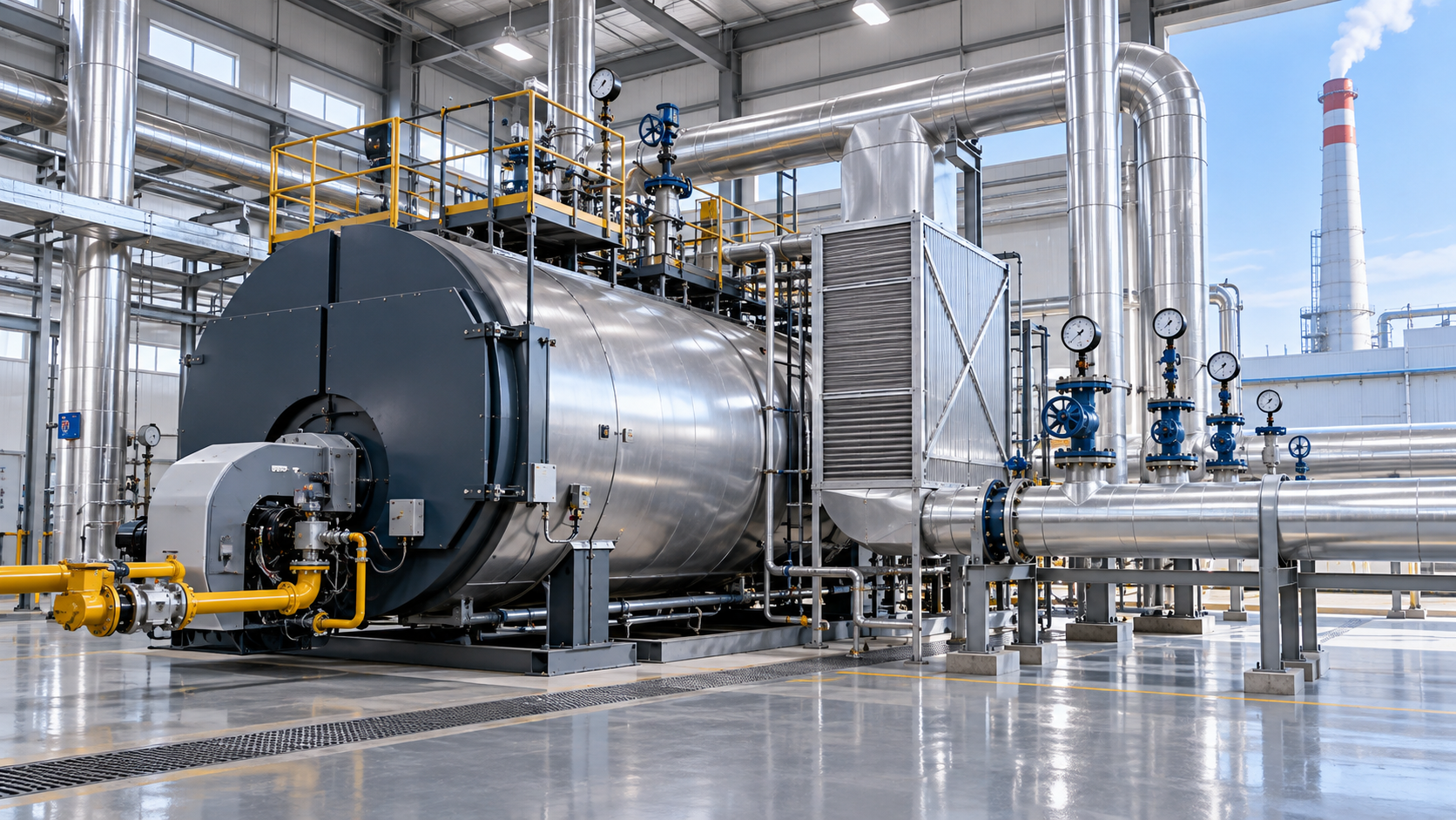
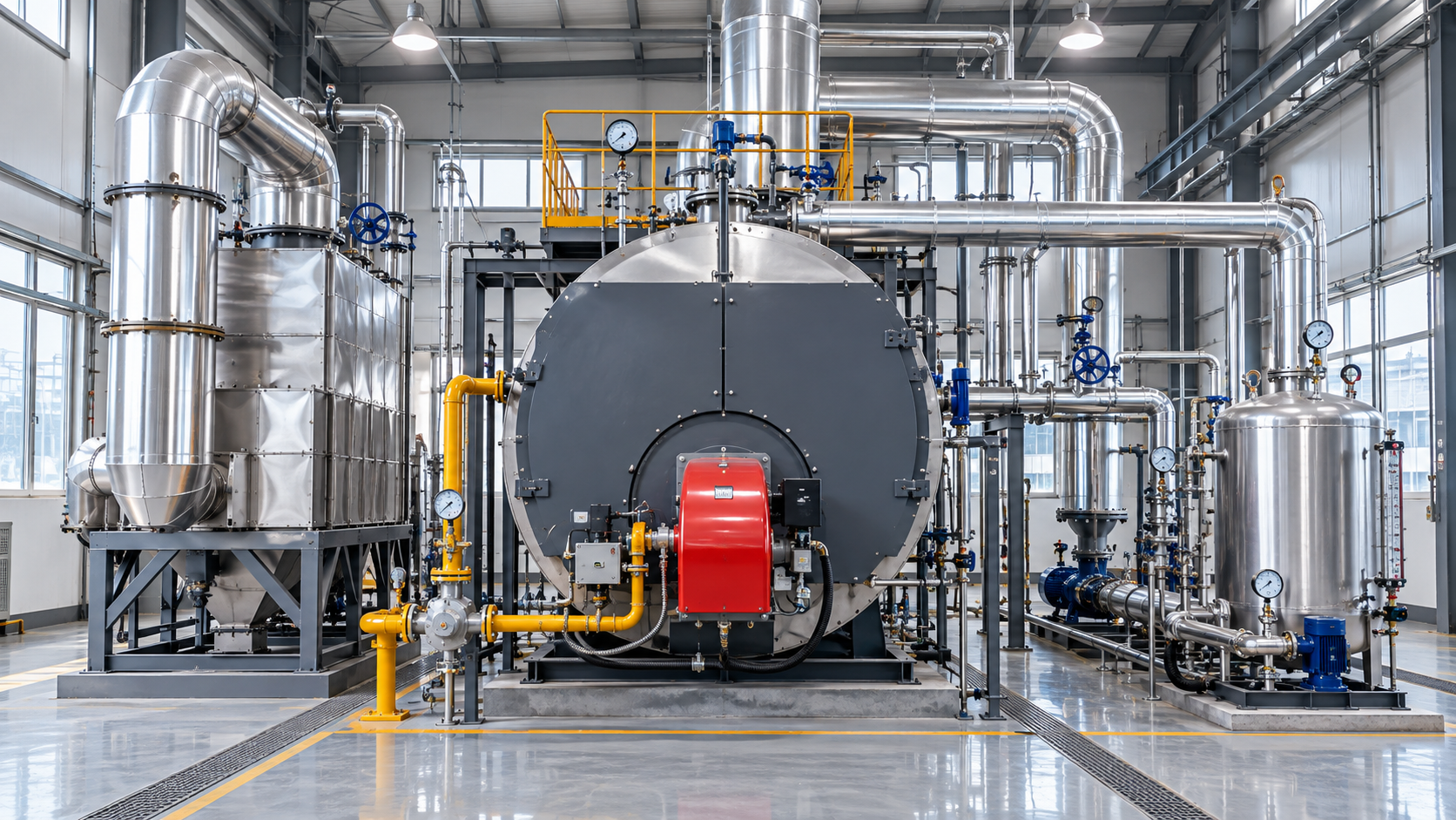
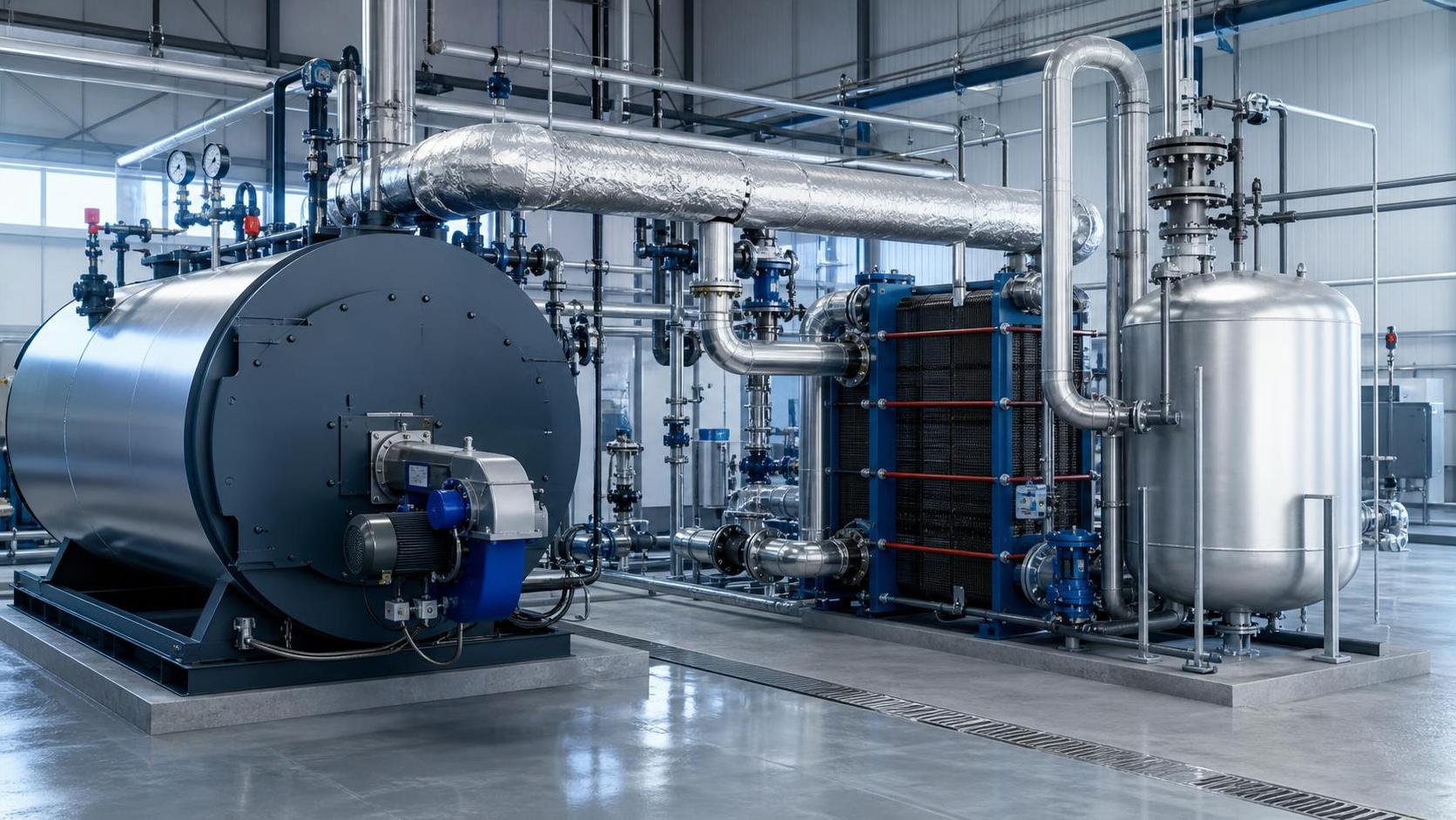
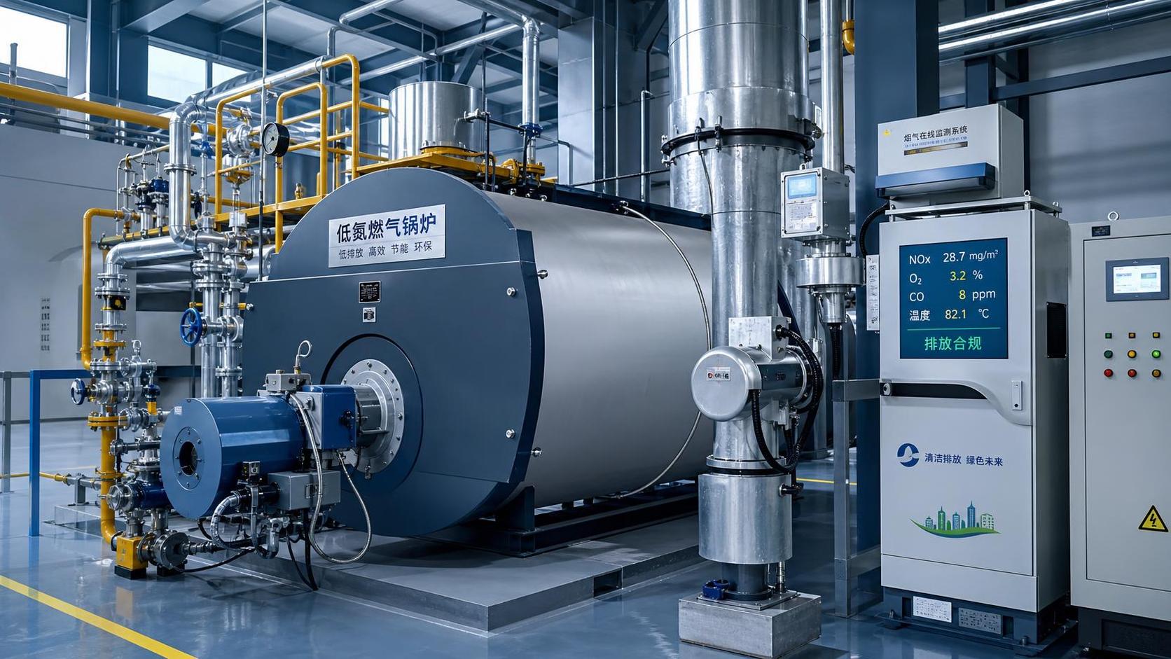
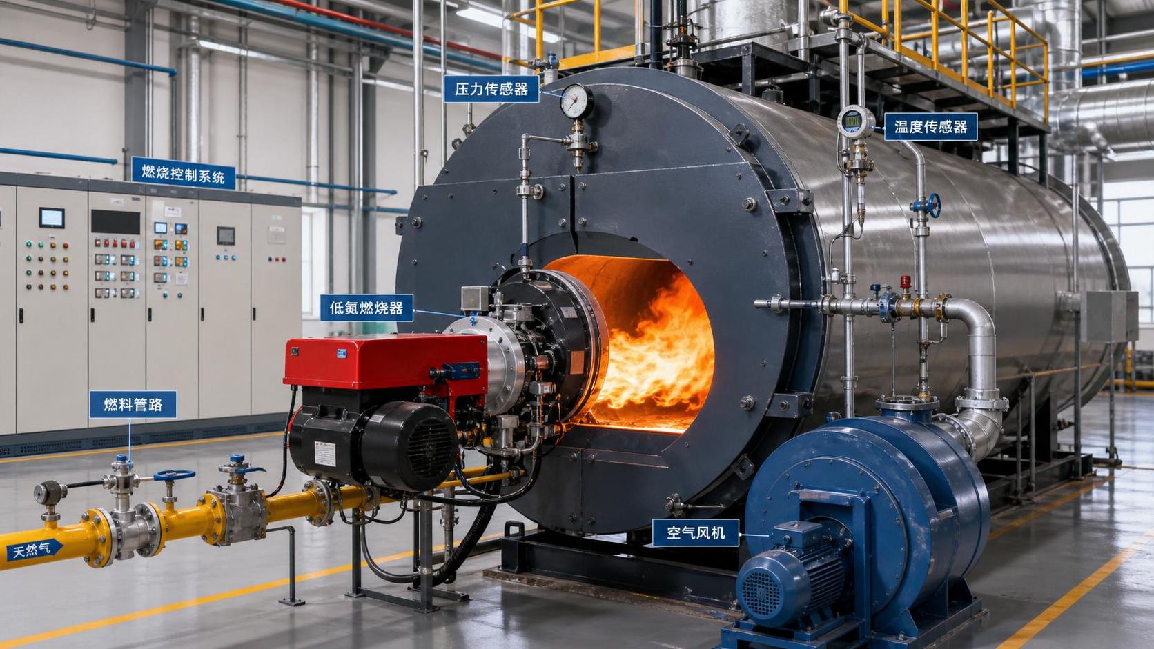
Many existing boiler heat recovery systems look complete on a process diagram: an economizer is installed, condensate is returned, blowdown heat is recovered, and flue gas temperatures appear lower than they were before the retrofit. Yet fuel consumption remains stubbornly high. For maintenance teams, this is usually a sign that the recovery equipment is no longer transferring heat, controlling flow, or matching demand as intended.
Industrial boiler heat recovery should be treated as a working energy balance, not as a static piece of installed equipment. A clean economizer with the wrong feedwater flow can underperform. A condensate recovery system can lose value if flash steam is vented or contaminated condensate is diverted. A flue-gas condenser can create corrosion risk if its drain, water treatment, or operating temperature is poorly managed.
The first practical question is therefore not, “Does the plant have heat recovery?” It is, “Where does recoverable heat leave the plant today, and what prevents it from being used at the moment demand exists?”
Start With the Temperatures That Tell the Story
A diagnosis should begin with stable operating data, collected during a representative production period rather than during startup, shutdown, or an unusual load condition. The useful comparison is not a single flue-gas temperature or a boiler efficiency value displayed on the control panel. Maintenance personnel need to connect temperatures, flows, pressure, and load across the entire recovery path.
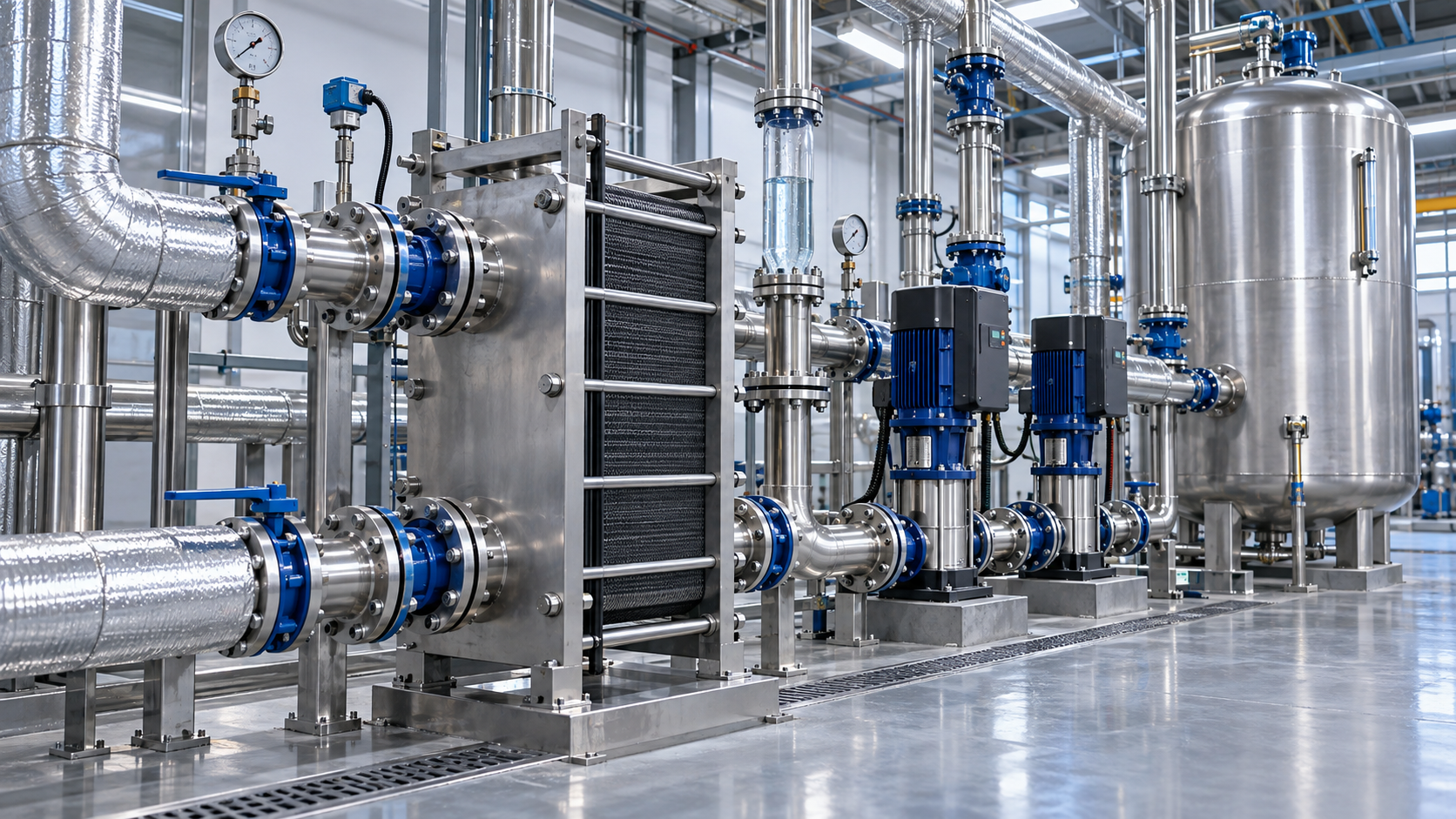
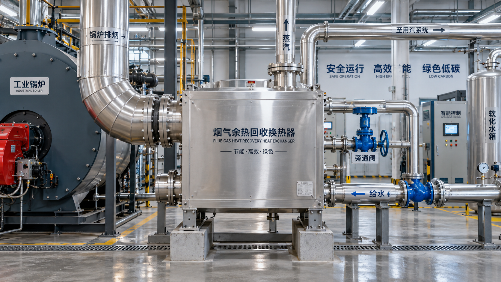
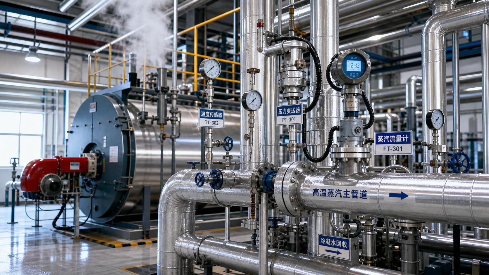
For a conventional economizer, the core readings are boiler firing rate, stack temperature downstream of the heat recovery section, feedwater temperature entering the economizer, feedwater temperature leaving it, and feedwater flow. If feedwater temperature rise is small while stack temperature remains elevated, heat transfer may be impaired or the water-side flow may be inadequate. If stack temperature is low but boiler fuel use has not improved, the recovered energy may be offset by excess fan power, unstable combustion, bypass leakage, or heat being added to water that the process cannot use.
Maintenance teams should also compare readings across shifts and production modes. A system that works during sustained high-load operation may provide little benefit when the boiler cycles, when feedwater demand falls, or when a process line is idle. Heat recovery capacity and heat demand must overlap in time. A recovered kilowatt of heat has little value when it is dumped, vented, or used to overheat a loop that later requires cooling.
Watch for a gradual rise in stack temperature at comparable boiler load. This commonly points to fouling on the gas side, scale on the water side, damaged baffles, bypassing around heat-transfer surfaces, or reduced water circulation. A sudden change is more likely to indicate an instrumentation fault, damper position problem, failed actuator, altered firing conditions, or a change in feedwater source.
Fouling Is Often a Control Problem Wearing a Maintenance Label
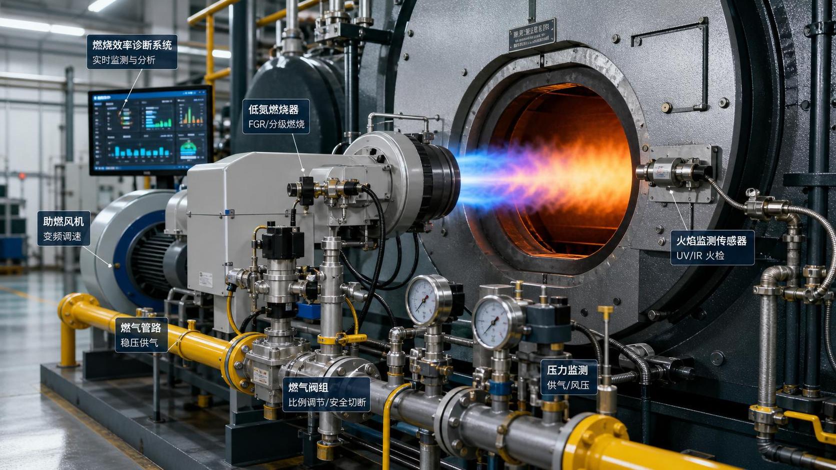
Fouling is frequently treated as a cleaning issue alone. Cleaning matters, but repeated fouling often has an upstream cause. On the gas side, poor combustion adjustment, burner degradation, excess carryover, air leakage, or particulate loading can reduce heat transfer and make deposits recur quickly. On the water side, hardness leakage, oxygen ingress, poor chemical control, or inadequate blowdown management can turn a recoverable heat surface into an expensive restriction.
An economizer can lose performance before the plant sees an obvious boiler alarm. Deposits raise thermal resistance, but they can also increase pressure drop. The resulting change in fan or pump duty may lead operators to reduce flow, open a bypass, or accept higher stack temperatures to keep production running. That operational workaround can remain in place long after the original deposit problem is addressed.
Inspection should therefore include more than surface condition. Review differential pressure across the heat exchanger, actuator positions, bypass damper travel, cleaning history, water-treatment records, and the operating logic that responds to high outlet temperature or high pressure drop. A heat recovery train may be mechanically clean yet functionally bypassed because a protective control limit has become the normal operating state.
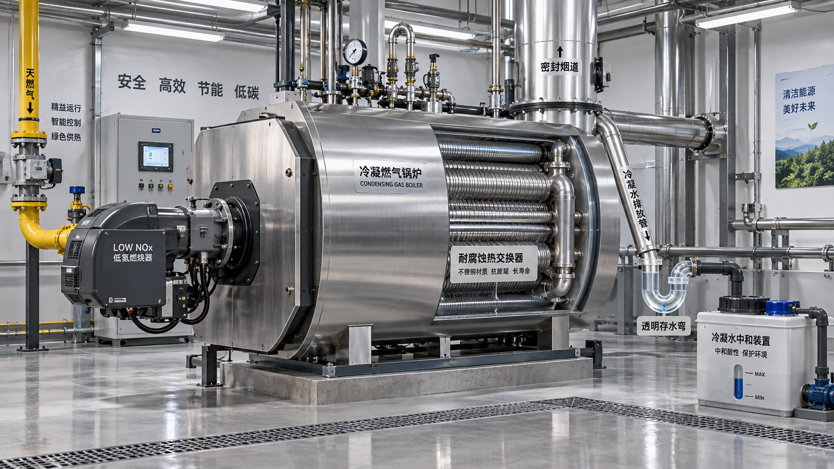
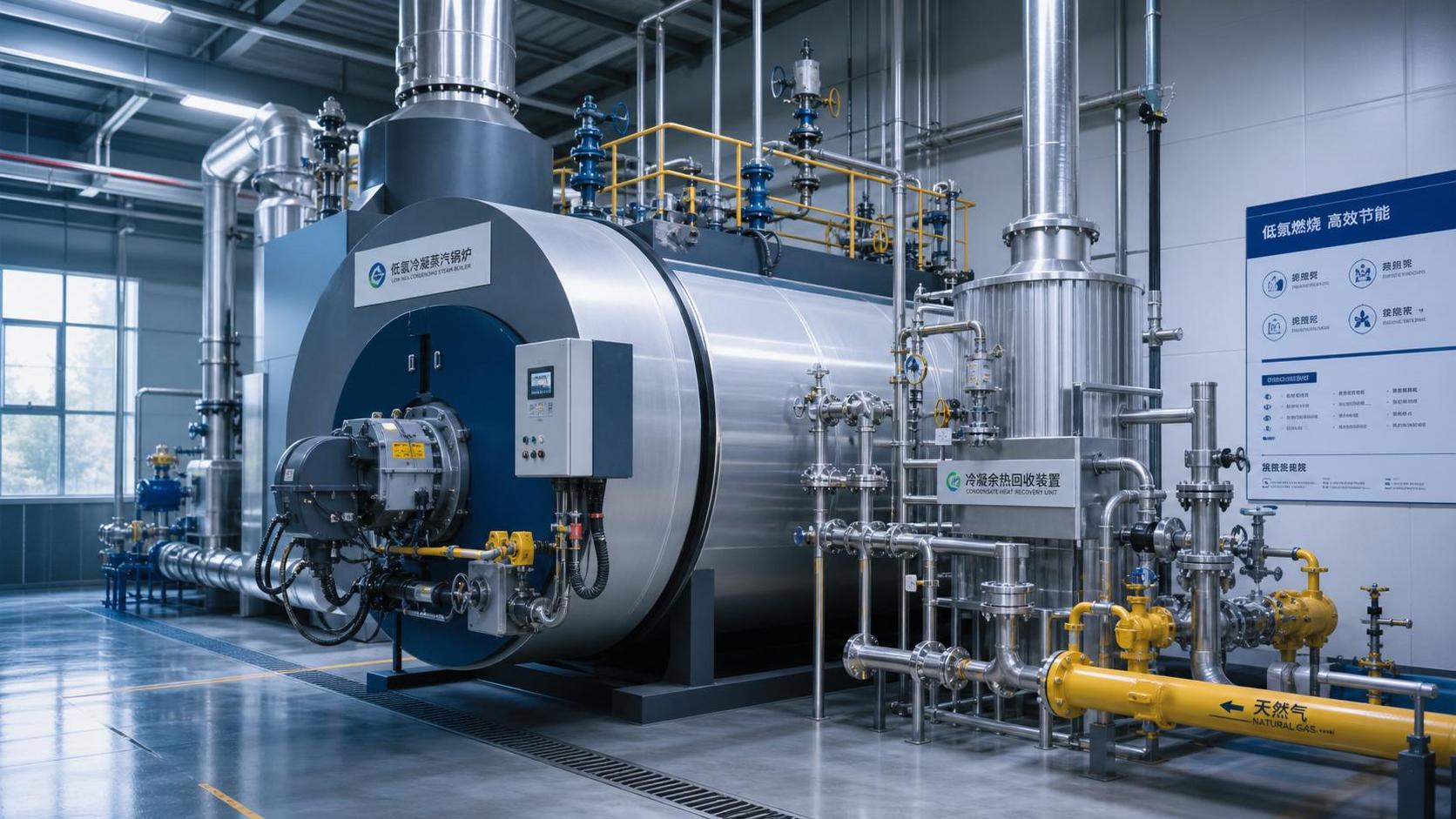
For condensing recovery equipment, deposits and corrosion require separate attention. Lowering flue-gas temperature below its dew point can recover additional sensible and latent heat, but condensate management becomes part of the equipment's operating integrity. Drain paths must remain open, materials must suit the condensate environment, and the receiving water circuit must have a reliable use for low-grade heat. Persistent leakage, acidic condensate pooling, or unexplained corrosion should not be dismissed as routine aging; they can signal an operating condition outside the design envelope.
Trace Steam and Condensate Losses Before Adding More Hardware
Plants often focus on stack losses because the stack is visible and easy to measure. Steam-side losses can be just as consequential, particularly where condensate return is incomplete or pressure management is poorly coordinated. Every kilogram of hot condensate that fails to return may carry away sensible heat, treated water, and chemical value. It also forces the boiler plant to heat more make-up water.
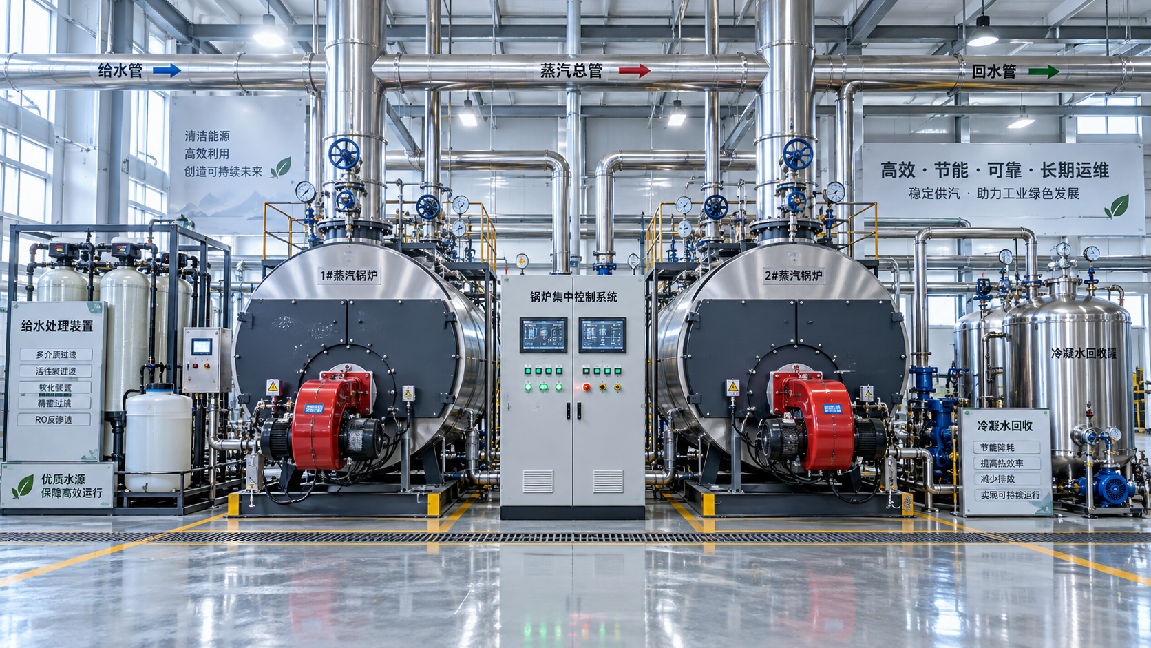
The diagnosis should follow condensate from the process back to the feedwater system. Identify where return flow drops, where pressure reductions occur, where flash steam is released, and where contamination concerns cause automatic diversion to drain. A return line can be physically connected yet provide limited benefit if traps fail open, receiver venting is excessive, transfer pumps cavitate, or condensate temperature is reduced unnecessarily before reuse.
Steam traps deserve attention, but a trap survey should not become an isolated maintenance exercise. A trap that passes live steam affects more than local energy loss. It can overload condensate equipment, increase flash losses, distort pressure conditions, and make downstream heat recovery look ineffective. Conversely, a trap that fails closed may reduce process heating and encourage operators to raise boiler pressure or open manual bypasses, increasing losses elsewhere.
Flash steam is another area where simple assumptions can mislead. Recovering flash steam is beneficial only when a suitable low-pressure steam user is available with adequate continuity. Routing flash steam into a header with unstable demand can create pressure disturbances, venting, or control conflicts. The maintenance question is not simply whether a flash vessel exists, but whether its outlet pressure, receiver capacity, control valves, and downstream users still align with the plant's operating profile.
Controls Can Quietly Erase a Sound Heat-Recovery Design
In older plants, the control sequence is often the least visible source of lost savings. Boiler controls may have been changed after a burner replacement, a process expansion, a water-treatment upgrade, or a safety modification. Each change may be reasonable on its own, while the combined result leaves the recovery system operating in a narrow and inefficient range.
Common examples include feedwater temperature limits that force economizer bypassing, minimum-flow settings that circulate more water than the heat sink requires, fan controls that maintain excessive excess air, and boiler sequencing that keeps several units lightly loaded instead of operating fewer units near their efficient range. A heat recovery system cannot compensate for poor load allocation.
Review the actual control logic, alarm history, and manual overrides rather than relying only on the original control narrative. A bypass valve shown as normally closed in documentation may be routinely held open. A temperature sensor with drift may keep a damper in a protective position. A failed valve-position feedback signal may cause an operator to run a loop manually. These are small defects individually, but they are precisely the defects that make installed recovery equipment appear disappointing.
A useful field exercise is to observe the plant through several changes in demand: a production line starting, a batch ending, a second boiler coming online, or a condensate receiver reaching a high level. The purpose is to see whether heat recovery responds in a controlled way or whether it is defeated by bypasses, venting, oscillation, and manual intervention.
Separate Recoverable Heat From Useful Heat
Maintenance teams are often asked to identify “waste heat,” but the more valuable distinction is between technically recoverable heat and heat that can be used without creating another operating burden. High-temperature flue gas may be suitable for feedwater preheating, combustion-air heating, process-water heating, or a lower-temperature loop. The best destination depends on temperature level, flow stability, water quality, seasonal demand, and the consequences of an interruption.
A recovery project can underperform when its heat sink is too intermittent. For example, process-water demand may disappear outside production hours, while the boiler continues to operate for other loads. In that condition, recovered heat may raise storage temperature without reducing fuel use, or it may trigger dumping, recirculation, or auxiliary cooling. The plant may report lower stack temperature while seeing little meaningful reduction in its energy bill.
Before recommending repairs or upgrades, map the available heat source and the receiving load over the same operating period. The following questions are usually more useful than a generic estimate of “recoverable energy”:
- Does the receiving load exist when the boiler is firing at meaningful rate?
- Can the receiving fluid accept the heat at the available temperature without upsetting process control?
- Will fouling, corrosion, contamination, or pressure drop create a maintenance burden that outweighs the expected gain?
- What happens when the heat sink is unavailable: bypass, storage, load reduction, or venting?
- Does the proposed recovery path affect boiler safety limits, combustion stability, or water-treatment requirements?
These questions are particularly important where operations have changed since the original recovery system was installed. A boiler plant may now serve different process temperatures, lower steam demand, altered shift patterns, or additional equipment that changes condensate quality. The physical equipment can remain intact while its original heat balance no longer exists.
Build a Repair List Around Loss Mechanisms
Once the diagnosis is complete, corrective work should be prioritized by the mechanism causing the loss. This prevents teams from spending heavily on new heat-transfer surface when the more immediate issue is a stuck bypass, inaccurate sensor, leaking steam trap, or unreliable condensate return pump.
The most defensible maintenance recommendation is one that links a measured loss to a specific operational consequence. “Clean the economizer” is weaker than “restore heat transfer and confirm that feedwater flow and bypass controls allow the recovered duty to be used.” “Improve condensate recovery” is incomplete unless the plan identifies where return is lost and whether the returned condensate can safely enter the feedwater system.
Use the Next Shutdown to Validate, Not Just Repair
A planned outage is the best time to inspect hidden surfaces, test dampers and valves through full travel, examine corrosion points, verify sensor condition, and confirm pipework routing. It should also be used to capture the baseline needed for post-maintenance comparison. Without a consistent before-and-after operating window, a repaired heat recovery system can be difficult to evaluate once production conditions change again.
After restart, monitor the same readings used in the diagnosis: fuel input, steam output, stack temperature, feedwater temperatures, pressure drop, condensate return, bypass position, and recovery-side demand. The objective is not to chase a single ideal temperature. It is to confirm that heat moves from the source to a usable load reliably across the operating conditions the plant actually sees.
That discipline turns industrial boiler heat recovery from an assumed efficiency feature into a maintainable energy system. In established plants, the largest opportunity is often already installed. It is found by locating the fouling, leakage, control behavior, and load mismatch that have allowed recoverable heat to escape unnoticed.
Related News
- Boiler Optimization: Cutting Fuel Use Without Compromising Steam ReliabilityAuthor :Thermal Energy Strategist

- How to size thermal fluid systems for stable process temperaturesAuthor :Thermal Energy Strategist

- Industrial Boiler Heat Recovery: Diagnosing Lost Savings in Existing PlantsAuthor :Thermal Energy Strategist

- Boiler Heat Recovery Systems: Sizing Waste-Heat Recovery for Stable Steam LoadsAuthor :Thermal Energy Strategist

- Can Condensing Boilers Cut NOx Emissions Without Creating Corrosion Risks?Author :Thermal Energy Strategist

- Low-NOx Boilers Industry Trends: What New Rules Mean for Plant UpgradesAuthor :Thermal Energy Strategist

- A Practical Roadmap for Industrial Steam System Decarbonization ProjectsAuthor :Thermal Energy Strategist

- Industrial Steam System Vendor Comparison: Criteria Beyond Equipment PriceAuthor :Thermal Energy Strategist

- How to Choose an Industrial Steam Generator for Load Profile, Fuel, and RedundancyAuthor :Thermal Energy Strategist

- When Does a Heat Recovery Steam Generator Make Economic Sense?Author :Thermal Energy Strategist

- How pressure control prevents unstable steam supply in industrial systemsAuthor :Thermal Energy Strategist

- How excess air affects boiler efficiency in steam systemsAuthor :Thermal Energy Strategist

- When a Refinery Steam Turbine Should Prioritize Process Steam Over Maximum OutputAuthor :Thermal Energy Strategist

- Which boiler upgrades deliver the fastest efficiency cost reductionAuthor :Thermal Energy Strategist

- What to check before choosing a steam generation systems supplierAuthor :Thermal Energy Strategist

- When do industrial boiler systems cost less than electric heatAuthor :Thermal Energy Strategist

- How to Compare Boiler Systems in Latin America by Fuel Cost and ComplianceAuthor :Thermal Energy Strategist

- How to Size Low-Pressure Industrial Steam Systems for Stable Heat DemandAuthor :Thermal Energy Strategist

- Low Emissions Boilers: What to Compare Before You ChooseAuthor :Thermal Energy Strategist

- Low-NOx Boilers Cost Breakdown: Upfront Price, Fuel Savings, and PaybackAuthor :Thermal Energy Strategist

- Boiler Combustion Systems: Common Causes of Unstable Fuel PerformanceAuthor :Thermal Energy Strategist

- Hot Water Industrial Boilers: When Efficiency Gains Justify ReplacementAuthor :Thermal Energy Strategist

- What Boiler Efficiency Really Means in Daily Operation and Energy BillsAuthor :Thermal Energy Strategist

- Boiler Efficiency Testing Methods That Expose Heat Loss and Fuel WasteAuthor :Thermal Energy Strategist

- Industrial Burner Systems: Key Factors for Safe Heat OutputAuthor :Thermal Energy Strategist

- Gas-Fired Boiler Combustion Technology: Key Efficiency and Emissions Trade-OffsAuthor :Thermal Energy Strategist

- Unfired Heat Recovery Steam Generators: When Do They Pay Off?Author :Thermal Energy Strategist

- How to Evaluate Steam Generation Systems Electric for Process Heat ProjectsAuthor :Thermal Energy Strategist

- Thermal Power Systems for Industrial Heating: Common Sizing Mistakes to AvoidAuthor :Thermal Energy Strategist

- Low-NOx Condensing Boilers: How to Compare Efficiency and EmissionsAuthor :Thermal Energy Strategist
![]()
- Low Emissions Boilers for Food Processing: Key Compliance and Fuel Cost FactorsAuthor :Thermal Energy Strategist

- Steam System Efficiency Calculation: Key Inputs That Change the ResultAuthor :Thermal Energy Strategist

- How to Evaluate a Steam Boiler Components Exporter Before OrderingAuthor :Thermal Energy Strategist

- Burner Systems Troubleshooting: Common Efficiency Loss CausesAuthor :Thermal Energy Strategist

- EU PED Q2 Rules Require Digital Compliance TagsAuthor :Thermal Energy Strategist

- Thermal Power Systems: Key Efficiency Risks in Daily OperationAuthor :Thermal Energy Strategist