



Boiler Heat Recovery Systems: Sizing Waste-Heat Recovery for Stable Steam Loads




Stable steam demand creates a strong case for recovering boiler flue-gas heat, but only when the recovery duty is sized around the real operating envelope rather than a single rated-load calculation. An oversized system can create low-temperature corrosion, unstable feedwater conditions, bypass losses, and difficult commissioning. An undersized system leaves fuel savings unrealized while still adding ductwork, controls, and maintenance obligations.
The practical sizing question is therefore not simply how much heat exists in the stack. It is how much heat can be transferred reliably to an acceptable sink while the boiler cycles through normal load changes, fuel variations, startup periods, and maintenance states. For a stable steam load, that answer is often more favorable because the recovered heat has a predictable destination. Yet stability in steam consumption does not automatically mean stability in flue-gas flow, feedwater temperature, or condensate return.
Start with the operating load band, not boiler nameplate capacity
A boiler rated for a certain steam capacity may spend most of its life well below that point. Heat-recovery equipment sized from maximum firing rate alone can be poorly matched to the dominant condition. The heat exchanger then sees lower gas velocity and lower available temperature difference during normal operation, while the water side may receive too little useful energy to justify the pressure drop or control complexity.
Build the design basis from logged operating data where available. The useful record includes steam flow, firing rate, stack temperature, feedwater temperature, condensate-return fraction, blowdown pattern, excess oxygen, and operating hours at each load range. A short period of unusually high production should not determine exchanger surface area unless it represents the intended permanent duty.
For a relatively flat steam load, select a recovery duty that remains useful at the lowest expected sustained boiler firing rate. The maximum-load case still matters for mechanical design, gas-side pressure drop, damper sizing, and water-side relief provisions, but it should not be the only thermal point. A recovery package that performs well only at peak output may require frequent bypass operation during ordinary production.
Separate steam stability from feedwater stability
Steam demand can remain nearly constant while feedwater conditions fluctuate sharply. A site with variable condensate return may have feedwater temperatures that move with process conditions, tank level, flash steam recovery, or makeup-water use. This changes the cold-side inlet temperature and directly changes the amount of flue-gas energy that the economizer can absorb.
When feedwater enters colder than expected, the exchanger can recover more heat, but the flue-gas outlet temperature may approach a corrosive range. When feedwater arrives hotter, the available temperature driving force falls and the expected duty declines. Neither condition should be treated as a fault by itself. The design must define permitted inlet-temperature limits and establish what the control system will do when they are exceeded.
A feedwater economizer is generally the clearest arrangement when the boiler has a continuous, controllable feedwater flow and sufficient pump head. If the feedwater flow is intermittent, or if the boiler runs with a large deaerator storage volume and irregular pump cycles, a separate circulating-water loop or thermal buffer may provide steadier exchanger operation. That arrangement adds pumps, controls, and another heat-transfer step, so it should be chosen only when it resolves a real mismatch.
The heat sink sets the usable recovery limit
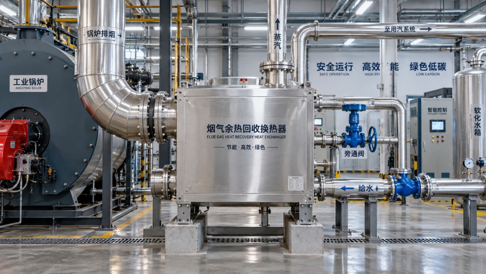
Flue gas contains recoverable sensible heat, and sometimes latent heat from water vapor. The usable portion is restricted by the temperature and flow of the receiving stream. Heating boiler feedwater, combustion air, makeup water, process water, or a closed heating loop each produces a different temperature profile. A high-temperature sink may accept heat near the boiler outlet but leave little driving force at the cold end of the exchanger. A low-temperature sink can capture more energy but may force the flue gas below its safe dry operating temperature.
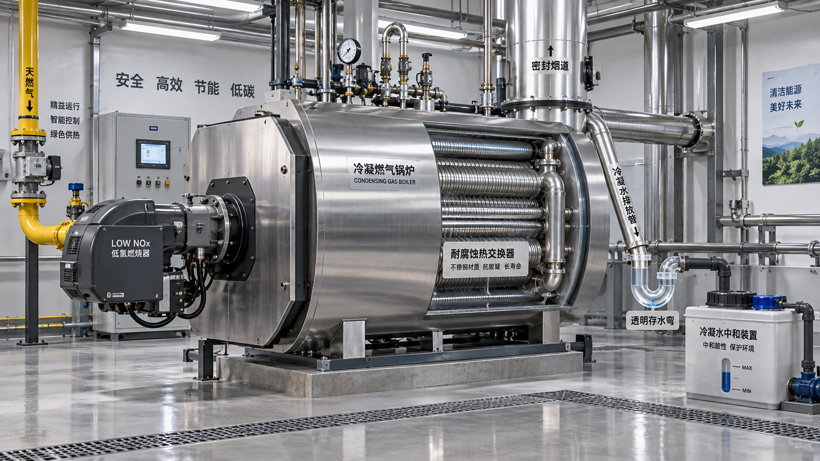
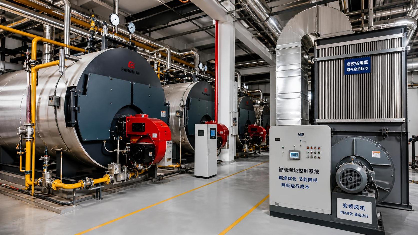
The first decision is whether the project is pursuing sensible recovery or condensing recovery. Sensible systems commonly use an economizer or air preheater and keep the gas outlet above the point where acid-bearing compounds and water vapor are likely to condense on heat-transfer surfaces. Condensing systems intentionally cool the gas further and require a design that manages acidic condensate, drainage, water treatment, and corrosion-resistant materials.
Fuel composition matters here. Fuels containing sulfur compounds can produce acidic condensate when the gas-side surface temperature drops too low. Even with a clean gaseous fuel, water condensation changes material and drainage requirements. A stack temperature that appears attractive in a simple energy balance may be unacceptable once local tube-wall temperature, load turndown, and cold-start behavior are considered.
Use a temperature profile, not an average temperature
Average stack temperature is useful for screening, but it is not enough to select equipment. Heat transfer changes along the exchanger length. The hot end, cold end, tube wall, and receiving-fluid temperatures need to be considered together. A design based solely on inlet and outlet averages can miss the local condition where condensation begins or where a feedwater stream approaches its allowable temperature limit.
A counterflow arrangement often offers better thermal effectiveness than parallel flow, but pipe routing, cleaning access, drainage direction, and pressure containment may favor a different geometry. The selected configuration should show the minimum temperature approach at the controlling end and the predicted metal temperature under low-load operation. That low-load calculation is especially important when boiler firing drops but cold water remains available.
Flue-gas recirculation, burner turndown, changes in excess air, and fouled convective surfaces can all alter stack conditions. High excess air increases gas mass flow but may lower gas temperature. A fouled boiler may raise stack temperature and make the recovery unit appear more productive, even though the boiler itself is losing efficiency upstream. Recovery performance should therefore be evaluated alongside boiler cleanliness and combustion condition, not as an isolated energy number.
Pressure drop is a system constraint, not a vendor detail
Every heat-recovery exchanger adds resistance to flue-gas flow. If the boiler has limited induced-draft capacity, added gas-side pressure drop can reduce firing capability, disturb combustion, or require fan modifications. A proposed exchanger should be assessed at clean and fouled conditions, at maximum firing rate, and with the bypass path in its intended position.
Water-side pressure drop deserves equal attention. An economizer installed in a feedwater line can change pump operating point and available pressure at the boiler inlet. Where feedwater is close to saturation temperature, inadequate pressure margin can produce flashing or cavitation risk. A restriction that appears minor in a thermal proposal can become a reliability issue once it is added to valves, strainers, flow meters, and existing piping losses.
Specify allowable pressure drop as a project input rather than allowing it to emerge from the exchanger design. This prevents a compact, high-velocity unit from being selected solely because it has attractive heat-transfer area per unit volume. Lower velocity may require a larger package but can reduce fan power, erosion, and fouling sensitivity.
Material selection follows the lowest credible surface temperature
Carbon steel may be appropriate for dry, non-corrosive gas service when the design preserves safe metal temperatures. It becomes a poor assumption when condensate is expected or when acid dew point cannot be reliably avoided. Stainless alloys, coated surfaces, polymeric components in suitable low-temperature duties, and corrosion-resistant drains are selected according to the actual condensate chemistry and temperature, not simply because a unit is labeled “condensing.”
Materials must be consistent across the complete wetted path. A corrosion-resistant tube bundle does not solve a problem if downstream drain pans, supports, fasteners, condensate piping, neutralization equipment, or stack-liner sections are vulnerable. The same review applies to insulation. Wet insulation and trapped condensate can conceal external corrosion around casings, duct transitions, and low points.
For dirty gas streams, fouling characteristics influence both exchanger type and tube spacing. Tighter passages improve heat-transfer intensity but complicate cleaning and increase blockage risk. Soot-blowing arrangements, access doors, wash provisions, removable panels, and adequate maintenance clearance should be settled before the equipment layout is frozen. Retrofitting access after ductwork is installed is expensive and often leaves the exchanger harder to service than intended.
Control philosophy should be defined before final surface area
A heat-recovery unit needs a normal operating position, but it also needs credible responses to low feedwater temperature, sudden steam-load reduction, boiler trip, pump failure, high stack backpressure, and exchanger isolation. These conditions determine the bypass arrangement, valve authority, temperature instruments, and interlocks.
Gas-side bypass dampers protect the exchanger and preserve draft when the heat sink is unavailable. Water-side bypasses can prevent feedwater from becoming too hot or maintain minimum flow through a circulating loop. The two are not interchangeable. A water-side bypass leaves flue gas passing through the exchanger and may still expose it to low surface temperatures; a gas-side bypass reduces gas-side duty but requires good sealing and sufficient duct space.
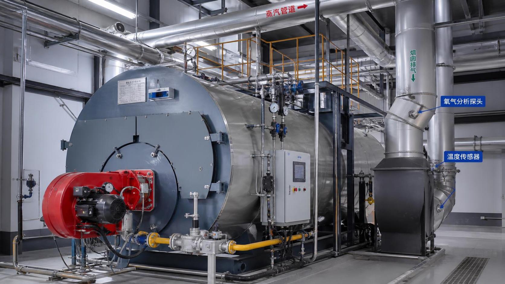
Controls should avoid chasing minor temperature changes with large damper movement. Slow thermal response, sensor placement, and actuator resolution matter. A sensor located far downstream of a mixing point can create delayed feedback and cycling. Temperature measurement near the actual exchanger inlet and outlet, combined with steam-flow and feedwater-flow signals where justified, gives a more dependable basis for control.
Integration details that frequently change the selected size
Available space often determines whether a theoretically efficient design is installable. Existing stack elevation, roof penetrations, structural loads, crane access, duct expansion allowances, and maintenance withdrawal paths can limit exchanger geometry. A short shutdown window may favor modular sections, though more field joints introduce additional leakage and insulation work.
Thermal expansion must be accommodated in ductwork and piping. An exchanger rigidly connected between existing duct sections can transmit expansion loads into casings, stack supports, or boiler connections. Expansion joints need proper alignment and support; they are not a substitute for poor load-path design. Condensate-producing equipment also requires continuously sloped drains, freeze protection where relevant, and no dead legs that retain acidic liquid.
Commissioning should verify more than outlet temperatures. Baseline draft, fan current, combustion oxygen, feedwater pressure, stack temperature, bypass leakage, drain function, and control response establish whether the installed system matches the design assumptions. A lower stack temperature is not automatically a successful result if it comes with unstable combustion, excessive fan demand, or early condensate formation in an unprotected downstream section.
A defensible sizing basis
A well-founded selection document states the normal steam-load band, maximum and minimum firing conditions, expected feedwater-temperature range, heat-sink availability, allowable gas-side and water-side pressure drops, fuel characteristics, target flue-gas outlet limits, fouling allowance, bypass duty, materials boundary, and maintenance access requirements. It also identifies which values are measured, which are estimated, and which will be confirmed during detailed engineering.
That level of definition keeps the recovery system tied to stable steam production rather than to an optimistic heat-balance snapshot. The selected duty can then be judged against the conditions it must survive: routine load variation, changing condensate return, combustion adjustment, fouling, and isolation events. Durable fuel savings follow from that operating fit, not from selecting the largest exchanger that can be placed in the flue path.
Related News
- Boiler Optimization: Cutting Fuel Use Without Compromising Steam ReliabilityAuthor :Thermal Energy Strategist

- How to size thermal fluid systems for stable process temperaturesAuthor :Thermal Energy Strategist

- Industrial Boiler Heat Recovery: Diagnosing Lost Savings in Existing PlantsAuthor :Thermal Energy Strategist

- Boiler Heat Recovery Systems: Sizing Waste-Heat Recovery for Stable Steam LoadsAuthor :Thermal Energy Strategist

- Can Condensing Boilers Cut NOx Emissions Without Creating Corrosion Risks?Author :Thermal Energy Strategist

- Low-NOx Boilers Industry Trends: What New Rules Mean for Plant UpgradesAuthor :Thermal Energy Strategist

- A Practical Roadmap for Industrial Steam System Decarbonization ProjectsAuthor :Thermal Energy Strategist

- Industrial Steam System Vendor Comparison: Criteria Beyond Equipment PriceAuthor :Thermal Energy Strategist

- How to Choose an Industrial Steam Generator for Load Profile, Fuel, and RedundancyAuthor :Thermal Energy Strategist

- When Does a Heat Recovery Steam Generator Make Economic Sense?Author :Thermal Energy Strategist

- How pressure control prevents unstable steam supply in industrial systemsAuthor :Thermal Energy Strategist

- How excess air affects boiler efficiency in steam systemsAuthor :Thermal Energy Strategist

- When a Refinery Steam Turbine Should Prioritize Process Steam Over Maximum OutputAuthor :Thermal Energy Strategist

- Which boiler upgrades deliver the fastest efficiency cost reductionAuthor :Thermal Energy Strategist

- What to check before choosing a steam generation systems supplierAuthor :Thermal Energy Strategist

- When do industrial boiler systems cost less than electric heatAuthor :Thermal Energy Strategist

- How to Compare Boiler Systems in Latin America by Fuel Cost and ComplianceAuthor :Thermal Energy Strategist

- How to Size Low-Pressure Industrial Steam Systems for Stable Heat DemandAuthor :Thermal Energy Strategist

- Low Emissions Boilers: What to Compare Before You ChooseAuthor :Thermal Energy Strategist

- Low-NOx Boilers Cost Breakdown: Upfront Price, Fuel Savings, and PaybackAuthor :Thermal Energy Strategist

- Boiler Combustion Systems: Common Causes of Unstable Fuel PerformanceAuthor :Thermal Energy Strategist

- Hot Water Industrial Boilers: When Efficiency Gains Justify ReplacementAuthor :Thermal Energy Strategist

- What Boiler Efficiency Really Means in Daily Operation and Energy BillsAuthor :Thermal Energy Strategist

- Boiler Efficiency Testing Methods That Expose Heat Loss and Fuel WasteAuthor :Thermal Energy Strategist

- Industrial Burner Systems: Key Factors for Safe Heat OutputAuthor :Thermal Energy Strategist

- Gas-Fired Boiler Combustion Technology: Key Efficiency and Emissions Trade-OffsAuthor :Thermal Energy Strategist

- Unfired Heat Recovery Steam Generators: When Do They Pay Off?Author :Thermal Energy Strategist

- How to Evaluate Steam Generation Systems Electric for Process Heat ProjectsAuthor :Thermal Energy Strategist

- Thermal Power Systems for Industrial Heating: Common Sizing Mistakes to AvoidAuthor :Thermal Energy Strategist

- Low-NOx Condensing Boilers: How to Compare Efficiency and EmissionsAuthor :Thermal Energy Strategist
![]()
- Low Emissions Boilers for Food Processing: Key Compliance and Fuel Cost FactorsAuthor :Thermal Energy Strategist

- Steam System Efficiency Calculation: Key Inputs That Change the ResultAuthor :Thermal Energy Strategist

- How to Evaluate a Steam Boiler Components Exporter Before OrderingAuthor :Thermal Energy Strategist

- Burner Systems Troubleshooting: Common Efficiency Loss CausesAuthor :Thermal Energy Strategist

- EU PED Q2 Rules Require Digital Compliance TagsAuthor :Thermal Energy Strategist

- Thermal Power Systems: Key Efficiency Risks in Daily OperationAuthor :Thermal Energy Strategist