



How to size thermal fluid systems for stable process temperatures




How to Size Thermal Fluid Systems for Stable Process Temperatures
Sizing thermal fluid systems correctly is essential for maintaining stable process temperatures, protecting product quality, and avoiding unnecessary energy use. The calculation is not simply a matter of selecting a heater or cooler with a nominal output above the stated process load. A thermal loop must respond to changing demand, overcome piping losses, circulate the right fluid at the right velocity, and remain controllable when the plant is operating outside its ideal design point.
For technical evaluators, the real challenge is balancing heat load, flow rate, fluid properties, equipment capacity, and control responsiveness under actual operating conditions. A system that is undersized may never reach setpoint during peak production. One that is oversized can short-cycle, create temperature oscillation, increase installed cost, and make stable control unexpectedly difficult.
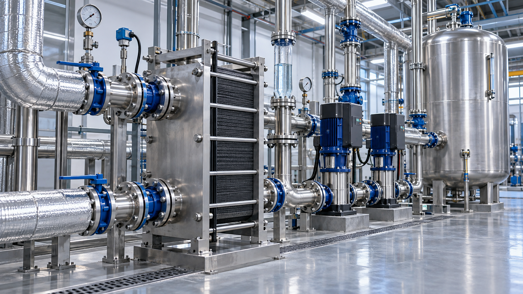
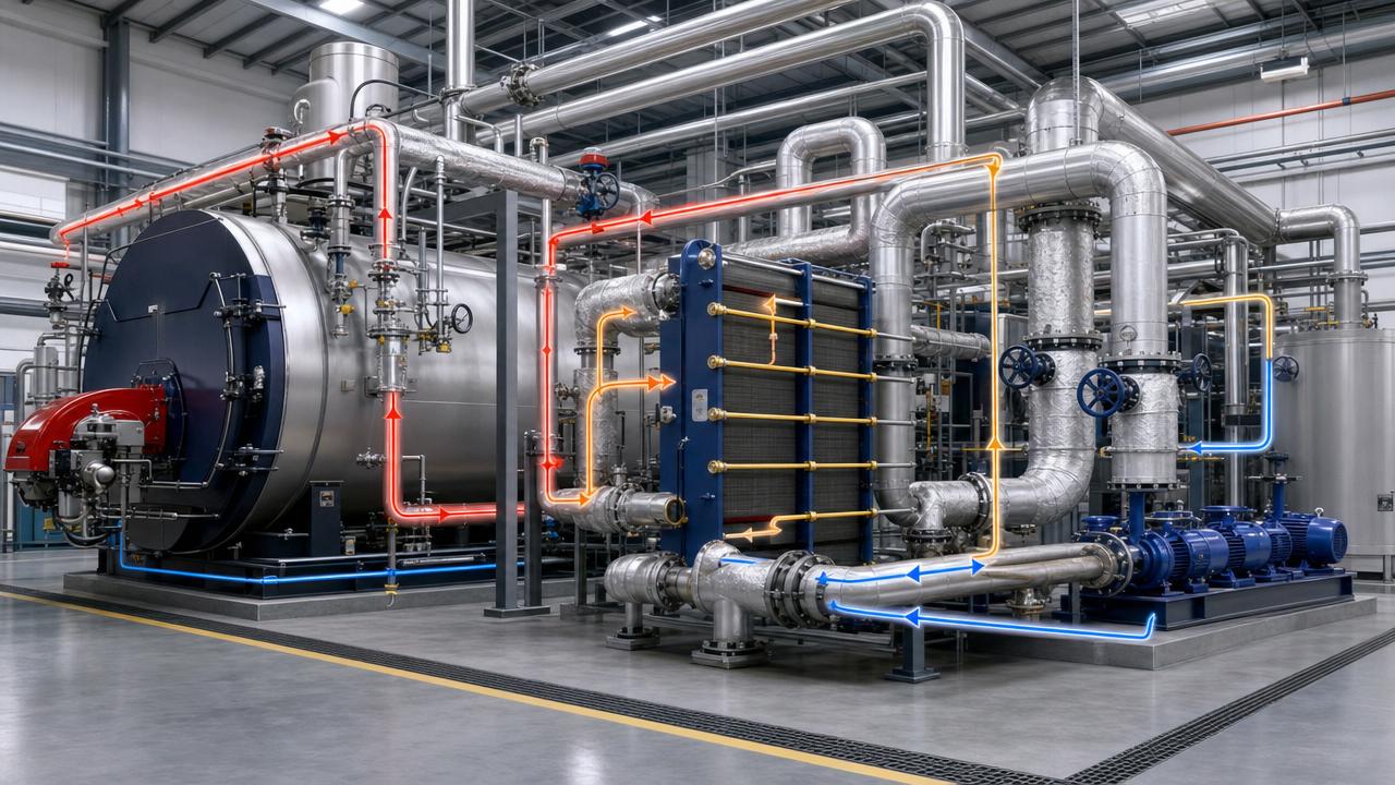
The most reliable approach is to size the complete thermal circuit: heat source or heat rejection equipment, circulating pump, expansion arrangement, piping, heat exchanger, controls, and the thermal fluid itself. Each part affects the others. A correctly selected chiller cannot compensate for a poor heat exchanger approach temperature, and a well-sized heater cannot deliver steady process conditions if pump flow is unstable.
Start with the process duty, not the equipment nameplate
The first question is whether the process needs heating, cooling, or both. Many industrial operations require more than one mode over a production cycle. A reactor may need heating for ramp-up, cooling during an exothermic reaction, and controlled holding afterward. An extrusion line may have a broadly steady cooling load but experience sharp peaks during start-up, grade changes, or upset recovery. These differences determine whether a single utility loop is sufficient or whether separate circuits, buffer capacity, or staged equipment are needed.
The fundamental thermal duty is commonly expressed as:
Q = m × Cp × ΔT
Where Q is heat transfer rate, m is mass flow rate, Cp is the specific heat capacity of the circulating fluid, and ΔT is the temperature change across the load. In practice, the equation is straightforward; establishing credible input values is harder. The thermal duty should include material heating or cooling, reaction heat where applicable, sensible heat in equipment and tooling, heat losses or gains from the environment, and expected peak operating conditions.
Nameplate data from a process machine can be useful, but it should not automatically be treated as the final design load. It may describe electrical connected load rather than actual heat rejection, or it may be based on a different ambient condition, production rate, or fluid temperature. When the process is not yet running, a mass and energy balance, supplier heat-duty information, and reasonable design assumptions should be documented rather than hidden inside a broad safety factor.
For batch processes, distinguish between average duty and transient duty. The average may govern annual energy consumption, while the short peak may govern pump capacity, heat exchanger area, chiller compressor staging, or heater output. Designing only around the average load is a common reason that a loop looks adequate on paper but struggles during the most critical part of the cycle.
Define the temperature window before choosing flow rate
Stable process temperature does not necessarily mean a fixed supply temperature. What matters is the allowable process band, the permitted temperature difference across the user, and the speed at which the system must correct a disturbance. A coating bath, a pharmaceutical vessel, and a hydraulic test stand may all need thermal control, but their tolerances and thermal inertia can be very different.
Once the process supply and return temperatures are established, the selected loop ΔT determines the required circulation rate. A smaller ΔT requires more flow to move the same amount of heat. Higher flow can improve heat transfer and temperature uniformity, but it also increases pumping energy, pressure drop, valve authority concerns, and the risk of erosion or noise in some systems. A larger ΔT reduces flow, yet may result in wider temperature variation at the process interface or an insufficient driving force in a heat exchanger.
The useful question is not “what flow is standard?” It is “what flow produces acceptable heat transfer and temperature control at the user while keeping pressure drop and operating cost sensible?” That answer should be evaluated against the actual exchanger geometry, jacket design, process-side fouling tendency, and control valve arrangement.
Fluid selection changes the sizing calculation
Water is often an efficient heat-transfer medium, but it is not automatically suitable. Freeze exposure, corrosion risk, process temperature range, contamination consequences, and local water quality all influence the choice. Water-glycol mixtures offer freeze protection but have different viscosity, heat capacity, and pumping characteristics from pure water. At low temperatures, the increased viscosity can substantially alter pressure-drop calculations and pump selection.
For elevated-temperature applications, synthetic or mineral-based heat-transfer fluids may be selected according to operating range, oxidation stability, vapor pressure, compatibility, and safety requirements. Their properties vary considerably with temperature. A pump that appears adequate based on a room-temperature viscosity may be wrong at cold start-up. Conversely, a system designed only for high-temperature circulation can overlook the fluid’s behavior during filling, commissioning, or winter shutdown.
Technical evaluation should therefore use supplier property data across the full operating envelope, including the minimum anticipated fluid temperature, normal operating temperature, maximum temperature, and any abnormal but credible condition. Important properties include density, specific heat, viscosity, thermal conductivity, vapor pressure, flash point where relevant, and recommended film temperature limits. The bulk fluid temperature alone is not enough: local film temperatures at heaters can be much higher and may accelerate fluid degradation if heat flux is excessive.
Size heat exchangers for real driving force and fouling
Heat exchangers are frequently selected by duty alone, even though duty does not define exchanger size. The available temperature driving force is equally important. In counterflow equipment, designers often use the log mean temperature difference, or LMTD, together with an overall heat-transfer coefficient and required duty. In more complex arrangements, a correction factor may be necessary. The calculation should reflect the actual flow arrangement, not an idealized one.
A tight approach temperature usually demands more exchanger surface area and closer attention to control. If the utility supply temperature is only slightly different from the process target, a small change in utility conditions can produce a noticeable process deviation. This is especially relevant when a central cooling-water network serves multiple users or when ambient conditions affect an air-cooled heat rejection system.
Fouling should be treated as a design condition, not merely a maintenance issue. Scaling water, polymer residues, oil contamination, or degraded thermal fluid can reduce heat-transfer performance over time. The appropriate allowance depends on fluid quality, equipment accessibility, filtration, treatment practice, and cleaning strategy. Excessively conservative fouling assumptions may create an unnecessarily large exchanger; ignoring credible fouling can leave no useful performance margin after months of operation.
Pump selection is a system-curve exercise
Pump sizing begins with required flow, but it is completed only after total dynamic head is calculated. The pump must overcome friction in straight pipe, fittings, hoses, control valves, filters, strainers, heat exchangers, jackets, elevation changes in non-closed arrangements, and any equipment that may become more restrictive as it fouls.
Pressure-drop estimates should be based on actual pipe diameters, expected fluid viscosity, and intended flow distribution. Long small-diameter branches may save material cost while imposing a lasting pumping penalty. In parallel users, unequal branch resistance can cause one load to receive excessive flow while another is starved. Balancing valves, differential-pressure control, or variable-speed pumping may be appropriate, but they need to be designed as part of the hydraulic scheme rather than added later to correct unstable behavior.
Net positive suction head also deserves attention, particularly with hot fluids, volatile liquids, elevated reservoirs, or suction-side restrictions. Cavitation is not simply a pump reliability issue; it can cause fluctuating flow and undermine temperature control before obvious mechanical damage is recognized.
Capacity margin should address uncertainty, not mask poor inputs
Some capacity margin is prudent because process loads, ambient temperatures, utility conditions, fluid aging, and future production demands rarely remain exactly as assumed. The problem is using a single large margin to cover every unknown. This can result in oversized compressors, heaters, pumps, and valves that operate inefficiently or control poorly at part load.
A better method is to identify uncertainty explicitly. Is the uncertainty in process heat generation, outdoor design temperature, fouling, future expansion, or start-up ramp rate? Each has a different response. A future expansion may justify spare connection points or modular equipment. A fluctuating cooling load may call for staged refrigeration capacity or a buffer tank. A short high-load event may require thermal storage rather than permanently oversized generation equipment.
Buffer volume is particularly useful when the load changes faster than the heat source or refrigeration circuit can modulate. It can reduce short cycling and soften transient swings, but it is not a universal cure. The tank must have enough usable thermal capacity at the allowed temperature swing, and its location, sensor placement, mixing behavior, and control sequence must be considered.
Control design determines whether calculated capacity becomes stable operation
A thermal system can meet its duty calculation and still be unstable. Control problems often arise from poorly placed sensors, oversized control valves, variable flow through equipment that requires minimum flow, or slow temperature feedback from a large vessel. The selected control philosophy should follow process dynamics.
For some loops, maintaining constant circulation through the user and modulating a secondary utility valve provides predictable heat transfer. For others, variable primary flow is appropriate, provided minimum flow and heat-source limitations are protected. Cascade control may help where the process temperature responds slowly but supply temperature changes quickly. Critical applications may also need separate monitoring of supply, return, process temperature, flow, pressure, and filter differential pressure so that a developing fault is visible before product conditions drift.
Do not overlook sensor accuracy, installation location, and response time. A precise sensor in the wrong location can lead a controller to react to a local temperature rather than the condition that matters to the process. Sensor wells, low-flow zones, and long transport delay between the heat exchanger and process can all affect tuning.
A practical review sequence before approving a design
Before committing to equipment, ask for a design basis that makes assumptions visible. It should show normal and peak duties, supply and return temperatures, selected thermal fluid and property basis, expected flow rates, exchanger approach temperatures, pressure-drop calculations, pump duty point, control concept, ambient design conditions, and anticipated maintenance requirements. If multiple operating modes exist, each should be checked rather than relying on one nominal point.
It is also worth confirming interfaces early: available electrical supply, water availability and quality, heat-rejection location, ventilation, drain and spill provisions, hazardous-area requirements where applicable, access for fluid sampling and exchanger cleaning, and the operating team’s ability to maintain the proposed arrangement. These are often treated as late-stage details, yet they can alter the preferred system architecture.
GTC-Matrix examines these decisions across industrial cooling, heat exchange, compression, and related utility systems because thermal performance is rarely isolated from the wider energy system. Its Strategic Intelligence Center follows technology and operating trends—from heat exchanger development to changing energy and refrigerant conditions—while keeping the engineering question grounded: what must the system do under real plant constraints?
The strongest thermal fluid system design is not the one with the largest nominal capacity. It is the one whose duty, fluid behavior, hydraulic resistance, heat-transfer surface, control response, and maintainability have been assessed together. For a final technical evaluation, require vendors and internal stakeholders to validate the design at minimum load, normal load, peak load, start-up, and credible upset conditions. That review is usually where hidden temperature-instability risks become visible.
Related News
- How to size thermal fluid systems for stable process temperaturesAuthor :Thermal Energy Strategist

- How to Choose an Industrial Steam Generator for Load Profile, Fuel, and RedundancyAuthor :Thermal Energy Strategist

- When Does a Heat Recovery Steam Generator Make Economic Sense?Author :Thermal Energy Strategist

- How pressure control prevents unstable steam supply in industrial systemsAuthor :Thermal Energy Strategist

- How excess air affects boiler efficiency in steam systemsAuthor :Thermal Energy Strategist

- When a Refinery Steam Turbine Should Prioritize Process Steam Over Maximum OutputAuthor :Thermal Energy Strategist

- Which boiler upgrades deliver the fastest efficiency cost reductionAuthor :Thermal Energy Strategist

- What to check before choosing a steam generation systems supplierAuthor :Thermal Energy Strategist

- When do industrial boiler systems cost less than electric heatAuthor :Thermal Energy Strategist

- How to Compare Boiler Systems in Latin America by Fuel Cost and ComplianceAuthor :Thermal Energy Strategist

- How to Size Low-Pressure Industrial Steam Systems for Stable Heat DemandAuthor :Thermal Energy Strategist

- Low Emissions Boilers: What to Compare Before You ChooseAuthor :Thermal Energy Strategist

- Low-NOx Boilers Cost Breakdown: Upfront Price, Fuel Savings, and PaybackAuthor :Thermal Energy Strategist

- Boiler Combustion Systems: Common Causes of Unstable Fuel PerformanceAuthor :Thermal Energy Strategist

- Hot Water Industrial Boilers: When Efficiency Gains Justify ReplacementAuthor :Thermal Energy Strategist

- What Boiler Efficiency Really Means in Daily Operation and Energy BillsAuthor :Thermal Energy Strategist

- Boiler Efficiency Testing Methods That Expose Heat Loss and Fuel WasteAuthor :Thermal Energy Strategist

- Industrial Burner Systems: Key Factors for Safe Heat OutputAuthor :Thermal Energy Strategist

- Gas-Fired Boiler Combustion Technology: Key Efficiency and Emissions Trade-OffsAuthor :Thermal Energy Strategist

- Unfired Heat Recovery Steam Generators: When Do They Pay Off?Author :Thermal Energy Strategist

- How to Evaluate Steam Generation Systems Electric for Process Heat ProjectsAuthor :Thermal Energy Strategist

- Thermal Power Systems for Industrial Heating: Common Sizing Mistakes to AvoidAuthor :Thermal Energy Strategist

- Low-NOx Condensing Boilers: How to Compare Efficiency and EmissionsAuthor :Thermal Energy Strategist
![]()
- Low Emissions Boilers for Food Processing: Key Compliance and Fuel Cost FactorsAuthor :Thermal Energy Strategist

- Steam System Efficiency Calculation: Key Inputs That Change the ResultAuthor :Thermal Energy Strategist

- How to Evaluate a Steam Boiler Components Exporter Before OrderingAuthor :Thermal Energy Strategist

- Burner Systems Troubleshooting: Common Efficiency Loss CausesAuthor :Thermal Energy Strategist

- EU PED Q2 Rules Require Digital Compliance TagsAuthor :Thermal Energy Strategist

- Thermal Power Systems: Key Efficiency Risks in Daily OperationAuthor :Thermal Energy Strategist

- Low-NOx Combustion Boilers: Key Efficiency and Compliance ChecksAuthor :Thermal Energy Strategist

- Low-NOx Combustion Boilers: Key Specs That Affect Emissions and Fuel UseAuthor :Thermal Energy Strategist

- Low-NOx Combustion Boilers: Key Compliance RisksAuthor :Thermal Energy Strategist

- Thermodynamics Analysis for Boiler Heat-Loss ReductionAuthor :Thermal Energy Strategist

- Industrial Thermal Systems: Common Operating RisksAuthor :Thermal Energy Strategist

- Low-NOx Combustion Boilers: Key Spec Checks Before PurchaseAuthor :Thermal Energy Strategist

- How Industrial Heat Recovery Cuts Boiler Fuel Costs in 2026Author :Thermal Energy Strategist