



How to Specify a High-Precision Temperature Chiller for Tight-Tolerance Processes




A tight-tolerance process can appear stable until a tool begins cycling, a recipe changes, or production shifts from a short run to continuous operation. At that point, a chiller that looked adequate on a nominal capacity sheet may allow fluid temperature to drift, overshoot after a load step, or oscillate around the setpoint. In semiconductor equipment, analytical instruments, laser systems, metrology, pharmaceutical processing, and precision manufacturing, those variations can affect dimensional control, measurement repeatability, reaction behavior, or uptime.
The core rule for specifying a high-precision temperature chiller is to begin with the process temperature requirement at the point of use, then work backward through the fluid loop, heat load profile, controls, and installation conditions. Do not select from temperature range and cooling capacity alone. The selected unit must maintain the required stability under the actual load changes, flow conditions, ambient conditions, and fluid properties of the application.
Start with the process tolerance, not the chiller setpoint
A request such as “maintain 20°C” is incomplete. The useful question is: how much variation can the process tolerate, where is that variation measured, and over what period? A temperature requirement at the chiller outlet is not automatically the same as the requirement at a laser head, platen, reactor jacket, test fixture, or instrument manifold.
Before reviewing equipment, define the following points with the process owner:
- Target process temperature: the required temperature at the actual controlled component or fluid inlet.
- Permitted deviation: the acceptable band around the target, expressed as a practical operating requirement rather than a vague request for “high precision.”
- Time basis: whether the limit applies over seconds, minutes, a process cycle, or an entire production shift.
- Measurement location: chiller outlet, return line, supply manifold, equipment inlet, product surface, or another defined point.
- Consequences of deviation: whether a short transient is acceptable, whether it invalidates a measurement, or whether it requires a process stop.
This distinction prevents a frequent specification error: accepting a published stability figure without confirming the test conditions behind it. A manufacturer may state temperature stability under steady load, fixed ambient temperature, defined flow, and measurement directly at the outlet. Those conditions can be valid, but they may not represent a process with intermittent heat release, long hose runs, changing flow rates, or equipment mounted in a warm enclosure.
Stability, accuracy, repeatability, and uniformity are different requirements
Temperature stability describes how tightly the controlled value remains near its setpoint over time. Accuracy describes how closely the displayed or controlled value corresponds to the true temperature. Repeatability concerns whether the system returns to the same result under comparable conditions. Uniformity addresses temperature variation across multiple points, such as a distribution loop, multi-zone fixture, or large thermal mass.
A process can have excellent outlet stability yet poor temperature uniformity at several remote loads. It can also have a stable but offset temperature if sensor calibration is not appropriate. Specify each characteristic separately where it matters. For instance, a tightly controlled analytical loop may need low temporal fluctuation and confidence in sensor accuracy, while a multi-tool cooling circuit may also need controlled distribution and balanced branch flow.
Build a heat-load profile before sizing capacity
Nominal cooling capacity should exceed the expected operating load with enough margin to accommodate realistic disturbances, but excessive oversizing can create its own control problems. A unit designed around a very large peak may cycle or hunt when the normal load is much lower, especially where the process has little thermal mass.
Separate the heat load into steady, transient, and environmental components. Steady load includes continuous motor losses, electronics dissipation, reaction heat, or heat conducted from a process. Transient load includes tool start-up, batch additions, rapid motion, laser duty-cycle changes, fixture loading, or periodic defrost-like events within the connected equipment. Environmental load includes heat absorbed through hoses, reservoirs, piping, and equipment exposed to room conditions.
A useful preliminary calculation is based on fluid flow and temperature rise:
Heat load = mass flow rate × fluid specific heat × temperature change.
Use measured or defensible operating values where possible. A design based only on pump nameplate flow can be misleading because actual flow depends on hose length, restrictions, valves, filters, quick-connects, elevation, and parallel branches. Likewise, the difference between supply and return temperature may be small during an averaged reading while short load events remain significant.
Ask for a load-versus-time profile rather than a single heat-load number. A process that rejects moderate heat continuously requires a different control approach from one that alternates between near-zero load and sharp peaks. The latter may need adequate buffer volume, staged capacity, variable-capacity refrigeration, controlled bypassing, or another arrangement that avoids repeated overcorrection.
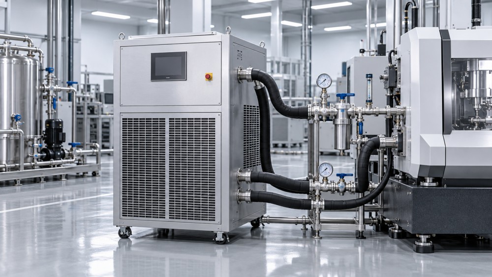
Match the chiller’s control response to the load dynamics
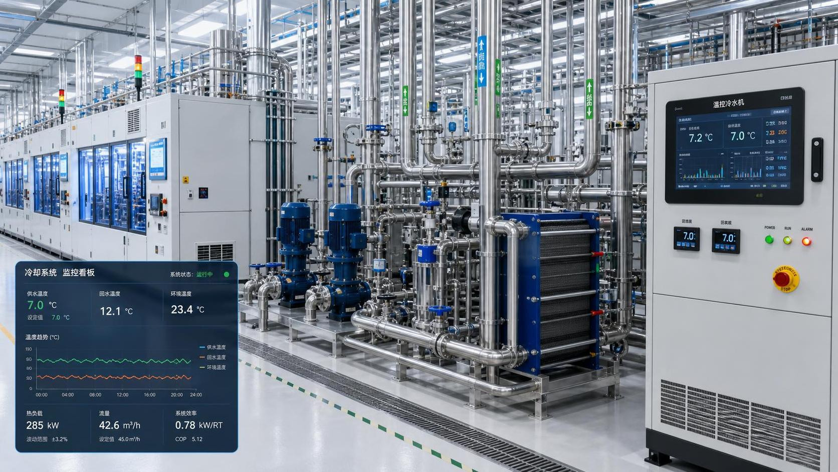
Precision cooling is not simply a refrigeration question. It is a control-loop question involving thermal mass, fluid volume, flow rate, sensor location, valve behavior, compressor or heater response, and the delay between a cooling action and a measured process change.
Consider a small recirculating loop serving a compact instrument. Its fluid volume may be low, and a change in cooling input can reach the controlled load quickly. Aggressive control tuning may cause overshoot or oscillation. A large loop with long piping behaves differently: it has more thermal inertia and transport delay, so a chiller outlet sensor can react to return conditions that originated several minutes earlier.
For tight tolerances, clarify how the unit controls temperature. Some systems rely on refrigeration cycling alone; others use a combination of cooling capacity modulation, hot-gas control, bypass control, electrical trim heating, or mixing arrangements. No single method is automatically best. The appropriate choice depends on the required band, load range, response time, and energy constraints.
Trim heating can be particularly relevant when the process load is low or variable. It allows the refrigeration side to operate in a controllable region while a heater removes small negative deviations. However, it adds energy consumption and must be evaluated as part of the operating philosophy rather than treated as a universal precision feature.
Specify the disturbance that matters
Instead of asking only for a stability value, describe the expected disturbances. Examples include a specified change in heat load, a change in return temperature, a pump-flow variation, a start-stop sequence, or a shift in ambient temperature. Then request information on settling behavior: how much the controlled temperature departs from its target, whether it overshoots, and how long it takes to return to the acceptable operating band.
This discussion is especially important when a process has alternating recipes or scheduled idle periods. A chiller may be stable during a constant-load qualification run but perform differently when the connected equipment releases heat in pulses. The selected configuration should be assessed against representative production behavior, not just the easiest test condition.
Define the fluid circuit as part of the equipment specification
The chiller and process loop form one thermal system. A highly capable temperature controller cannot compensate indefinitely for unstable flow, entrained air, poorly insulated pipework, or a fluid that is unsuitable for the required temperature range.
State the fluid type, concentration, and allowable cleanliness level. Water, water-glycol mixtures, dielectric fluids, and specialty process fluids differ in heat capacity, viscosity, corrosion behavior, and compatibility with pump seals, heat exchangers, hoses, fittings, and connected equipment. Increasing glycol concentration may provide freeze protection but generally changes pumping requirements and heat-transfer performance. That impact should be considered in both capacity and flow calculations.
Flow requirements deserve equal attention. Determine the required flow at the process inlet, minimum acceptable flow, maximum allowable pressure, expected pressure drop, and whether several loads operate in parallel. A pump with sufficient nominal flow may still fail to deliver the required condition after piping losses are included. Conversely, excessive pump pressure can damage sensitive channels, create leakage risk, or cause undesirable vibration and noise.
Filtration also needs a clear purpose. A filter can protect narrow passages and pumps, but a loaded filter increases pressure drop. The maintenance interval should be based on expected fluid cleanliness and accessible installation space, not added as a generic accessory without considering its hydraulic effect.
Check the temperature range against ambient and condensation risk
The required supply temperature must be evaluated alongside the minimum and maximum ambient conditions where the unit and piping will operate. A chiller located in a clean laboratory, an equipment bay, and a factory floor may face very different air temperatures, airborne contamination levels, ventilation constraints, and service access.
Cooling fluid below the local dew point can cause condensation on hoses, manifolds, valves, and process equipment. This is not merely a cosmetic issue. Moisture can affect electrical assemblies, insulation, precision surfaces, and cleanliness-sensitive equipment. If the target temperature approaches or falls below dew point, define whether insulation, vapor sealing, drip management, environmental control, or a higher process temperature is required.
Low-temperature applications also require freeze protection analysis. A fluid that remains usable during normal operation may become unsuitable during transport, shutdown, fault conditions, or exposure to a colder area. The selected fluid concentration, safety controls, and operating procedures should all align with the lowest credible temperature in the system.
Do not treat sensor placement as a minor detail
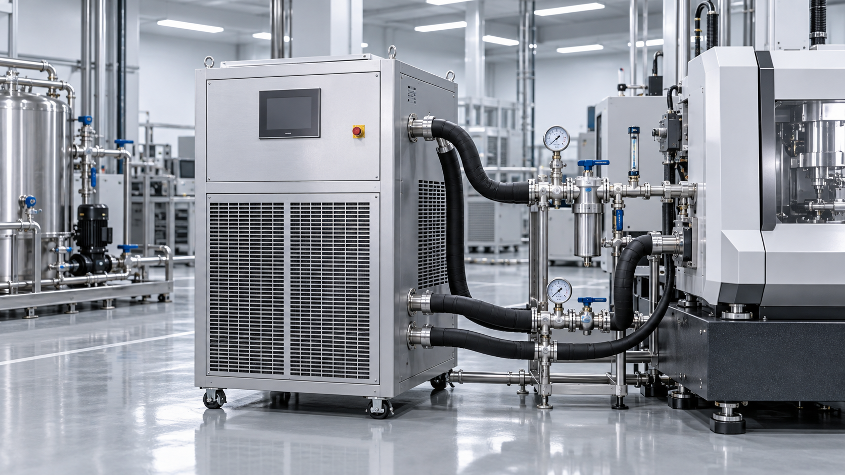
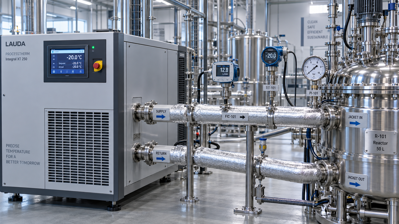
Most chillers control based on an internal sensor, often located near the outlet or reservoir. That arrangement may be appropriate for a simple loop, but it cannot directly correct a temperature change that occurs downstream due to long piping, heat ingress, or variable branch loading.
Where process temperature is critical, determine whether the control architecture supports a remote sensor at or near the point of use. Remote sensing can improve control relevance, but it also introduces longer delay and may require careful tuning. It should not be selected automatically; the value depends on whether the process is more sensitive to outlet temperature or to the actual condition at the connected tool.
Include sensor accuracy, calibration approach, resolution, sensor type, and fault behavior in the evaluation. A controller display with fine resolution does not prove equivalent measurement accuracy. Also determine what happens if a sensor opens, drifts outside a plausible range, or loses communication. For an unattended process, alarm handling and safe-state behavior may be as important as the normal control band.
Specify operating boundaries that can be verified at acceptance
A technically complete request should allow suppliers and internal reviewers to assess the same duty. It should state the target temperature, acceptable stability at a defined measurement point, fluid and flow details, heat-load profile, ambient range, power supply, installation constraints, communications needs, and required alarm functions. It should also identify whether cooling-water availability, air-cooled heat rejection, noise limits, or cleanroom-related restrictions affect the installation.
Where the tolerance is especially narrow, define a practical acceptance method before purchase. The method should identify the test fluid, flow condition, ambient condition, heat load, measurement instrument, sensor location, sampling interval, and test duration. Without this agreement, a system may meet a factory outlet-temperature test while failing to demonstrate the process-level performance that prompted the purchase.
Questions that expose weak specifications
- Is the stated stability measured at the outlet, reservoir, or process inlet?
- At what load percentage and flow rate was that performance established?
- Can the chiller remain controlled across the full expected load range, including idle periods?
- What capacity remains available at the required supply temperature and worst expected ambient?
- What pump pressure is available at the actual system resistance, not only at zero flow?
- Which materials contact the fluid, and are they compatible with the planned chemistry?
- How are alarms, remote monitoring, interlocks, and sensor faults handled?
These questions often reveal whether a request is based on process needs or only on a previous equipment model. Replacing an existing unit with the same nominal capacity may be reasonable, but only after confirming that process loading, piping layout, ambient conditions, and tolerance requirements have not changed.
When a single chiller is not the right architecture
One central unit is not always the best answer for multiple precision loads. A shared loop can be efficient and easier to maintain, yet it can also allow one tool’s changing heat load to influence another tool. Where loads have different temperature setpoints, incompatible fluids, sharply different duty cycles, or critical isolation requirements, separate loops or secondary control stations may provide better process control.
Similarly, adding reservoir volume can smooth rapid disturbances but may slow response to intentional setpoint changes. Increasing pump flow can reduce the temperature rise across a load, but it may increase pressure drop and exceed equipment limits. These are design trade-offs, not upgrades that should be applied by default.
A sound selection decision documents those trade-offs in process terms: required temperature at the load, credible disturbance range, acceptable recovery behavior, and maintainable installation conditions. When those elements are defined, the high-precision temperature chiller can be evaluated as a controllable part of the process rather than as a standalone cooling appliance.
Related News
- When do smart thermal systems with sensors reduce chiller energy use?Author :Cryogenic Systems Expert

- How to Specify a High-Precision Temperature Chiller for Tight-Tolerance ProcessesAuthor :Cryogenic Systems Expert

- Designing Energy-Efficient Industrial Cooling for Variable Process LoadsAuthor :Cryogenic Systems Expert

- Low-GWP Cooling Solutions for Process Plants: Comparing Safety, Efficiency, and CostAuthor :Cryogenic Systems Expert

- How to size energy efficient industrial cooling for a process loadAuthor :Cryogenic Systems Expert

- How to specify high-precision temperature control in EuropeAuthor :Cryogenic Systems Expert

- How cooling system design affects cleanroom contamination controlAuthor :Cryogenic Systems Expert

- When does industrial cooling heat recovery pay back in energy savings?Author :Cryogenic Systems Expert

- How to size an industrial cooling system for peak process loadsAuthor :Cryogenic Systems Expert

- When are aluminum electronics cooling solutions suitable for high-density designs?Author :Cryogenic Systems Expert

- A thermal management guide for preventing chiller capacity lossAuthor :Cryogenic Systems Expert

- When does aluminum make sense for electronics cooling solutions?Author :Cryogenic Systems Expert

- EU Battery Carbon Footprint Labels Become Mandatory on Aug 18 for Battery-Integrated Cooling and Energy Storage ExportsAuthor :Cryogenic Systems Expert

- China-UAE Direct Sea Route Cuts Lead Times for Industrial Cooling and Compression ExportsAuthor :Cryogenic Systems Expert

- EPA Rule Takes Effect for R-410A Equipment ImportsAuthor :Cryogenic Systems Expert

- EN 378-1:2026 Tightens EU Export ChecksAuthor :Cryogenic Systems Expert

- How to Compare Semiconductor Cooling Solutions by Heat Load and Uptime RiskAuthor :Cryogenic Systems Expert

- EU Label Deadline Hits China Chiller ExportsAuthor :Cryogenic Systems Expert

- How Smart Thermal Systems Improve Industrial Cooling EfficiencyAuthor :Cryogenic Systems Expert

- How to Choose Process Cooling Equipment for Stable Temperature ControlAuthor :Cryogenic Systems Expert

- EU Finalizes 2026 HFC Quota Cut for R-134a ChillersAuthor :Cryogenic Systems Expert

- EU Tightens HFC-134a Quotas for Industrial ChillersAuthor :Cryogenic Systems Expert

- REACH SVHC Update Pressures HFC-134a Chiller Supply ChainsAuthor :Cryogenic Systems Expert

- EU PFAS Coolant Ban Reshapes Chiller ExportsAuthor :Cryogenic Systems Expert

- EU REACH Restricts PFAS Cooling Media ImportsAuthor :Cryogenic Systems Expert

- EU Ecodesign Rule Takes Effect for Industrial ChillersAuthor :Cryogenic Systems Expert

- EU REACH Rule Takes Effect for PFAS in Industrial Cooling ExportsAuthor :Cryogenic Systems Expert

- Industrial Cooling for Plastic Processing: How to Size for Stable Cycle TimesAuthor :Cryogenic Systems Expert

- EU F-Gas Update Bars R404A/R507 in Commercial CoolingAuthor :Cryogenic Systems Expert

- DOE Raises Chiller Efficiency Standard From October 2026Author :Cryogenic Systems Expert

- India Mandates BIS Energy Certification for Industrial ChillersAuthor :Cryogenic Systems Expert

- Energy-Efficient Heat Exchange for Process Cooling: Cost vs PaybackAuthor :Cryogenic Systems Expert

- EPA R-134a Import Ban Takes Effect on July 13, 2026Author :Cryogenic Systems Expert

- India BIS Rule Takes Effect for Industrial ChillersAuthor :Cryogenic Systems Expert

- EPA Cuts R134a Import Quotas 20% From July 10Author :Cryogenic Systems Expert

- How to Compare Energy-Efficient Cooling Systems for Factory Expansion ProjectsAuthor :Cryogenic Systems Expert