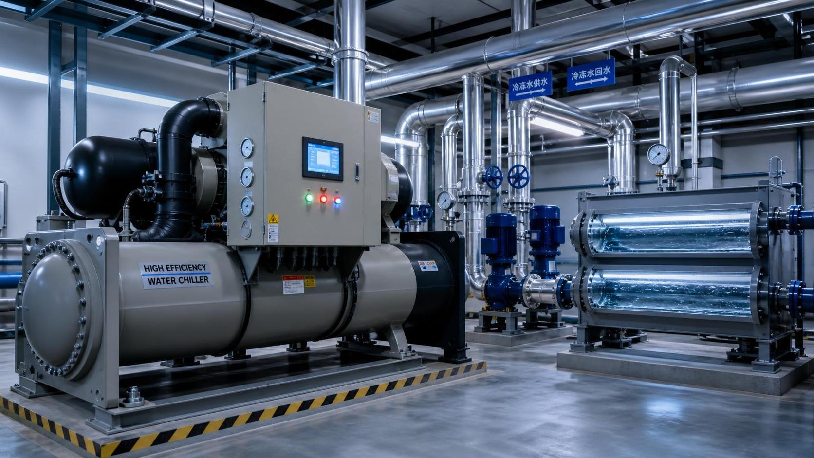




A thermal management guide for preventing chiller capacity loss




Chiller capacity loss is rarely a single-component failure. More often, it is the visible result of degraded heat transfer, incorrect flow conditions, unstable refrigerant operation, or controls that no longer match the process requirement. A unit may still run continuously, show no active alarm, and yet fail to maintain leaving-water temperature when load rises. Treating that condition as “low refrigerant” without verifying the thermal balance can turn a manageable maintenance issue into an unnecessary refrigerant intervention.
The practical objective is to determine where the cooling path is being restricted: at the evaporator, condenser, refrigerant circuit, water loop, air path, or control system. Capacity is not simply the compressor’s ability to run. It is the rate at which heat can be absorbed from the process and rejected to the ambient environment or condenser-water circuit. Any restriction in that chain reduces usable output.
Confirm that the chiller has lost capacity rather than the load has changed
Before diagnosing the machine, establish whether the apparent shortfall is caused by a real increase in process load. A production change, higher room temperature, warmer makeup water, new equipment on a common loop, reduced process-side flow, or a change in product cycle can all raise the heat load beyond the original operating point.
Start with operating data collected under stable conditions: leaving and entering evaporator-water temperatures, chilled-water flow, condenser entering and leaving temperatures, ambient temperature for air-cooled units, compressor loading, and the active control setpoint. Compare these values with prior records taken under comparable conditions rather than relying only on nameplate capacity. Nominal capacity is rated at specified evaporating and condensing conditions. It is not a guaranteed output under every field condition.
For a water-based evaporator circuit, cooling duty can be estimated from water flow and temperature difference:
Cooling load = mass flow × specific heat × temperature difference
If flow is known and the entering-to-leaving temperature difference is much smaller than expected, the process may not be transferring sufficient heat to the evaporator, or flow measurement may be incorrect. If the temperature difference is high but leaving-water temperature remains above setpoint, the chiller may be operating at or below its available capacity. This distinction prevents maintenance effort from being directed at the wrong side of the system.
Read the temperature pattern before adjusting refrigerant charge
Temperature relationships provide the fastest indication of where the thermal problem is developing. Refrigerant pressures are useful, but pressure values alone do not explain whether poor performance is caused by heat exchanger fouling, flow loss, non-condensables, a restriction, or a control issue.
On the evaporator side, compare leaving-water temperature with saturated evaporating temperature. The difference between them is commonly described as evaporator approach. A rising approach under similar load and flow conditions suggests that heat transfer has deteriorated. Fouling, scale, low water flow, air trapped in the circuit, a partially closed valve, or poor refrigerant distribution can contribute.
On the condenser side, compare saturated condensing temperature with the temperature of the heat-rejection medium. For an air-cooled chiller, the relevant reference is entering-air temperature. For a water-cooled chiller, it is entering condenser-water temperature. A higher-than-normal condenser approach indicates that heat is not being rejected efficiently. The compressor then works against a higher condensing pressure, draws more power, and may unload or trip on high-pressure protection before the required cooling output is reached.
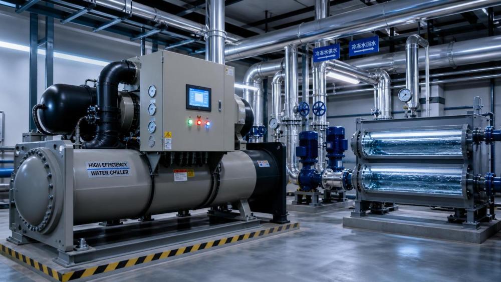
A useful diagnostic rule is to look for the side of the system that is forcing the refrigerant temperature away from the medium it is meant to exchange heat with. A warm condenser does not automatically mean an overcharged system; dirty coil surfaces, weak fan performance, recirculated hot air, insufficient condenser-water flow, or elevated cooling-tower return temperature can produce a similar symptom.
Restore heat transfer at the evaporator without creating a flow problem
Evaporator performance depends on clean heat-transfer surfaces, correct water velocity, stable flow, and effective control of freeze risk. The maintenance task is not merely to obtain a low leaving-water temperature. It is to maintain heat transfer without allowing local refrigerant temperatures to fall into a range that can freeze water inside the exchanger.
Check strainers, filters, and isolation valves before assuming internal fouling. A partially blocked strainer can reduce evaporator flow enough to create a high water temperature difference and unstable suction conditions. Differential-pressure readings across the evaporator and across strainers are more useful than visual inspection alone when connection points are available.
Air in a hydronic circuit creates additional problems beyond reduced flow. It can collect in high points, interfere with pump operation, cause fluctuating differential pressure, and leave portions of the evaporator insufficiently wetted. Symptoms may include erratic leaving-water temperature, nuisance low-temperature alarms, pump noise, or repeated flow-switch events. Verify expansion tank condition, automatic air vents, system pressure, and the location of any manual venting points.
Water quality matters because even a thin deposit can reduce heat transfer and raise evaporator approach. The appropriate cleaning method depends on exchanger material, deposit type, treatment chemistry, and manufacturer guidance. Mechanical cleaning, chemical descaling, flushing, and passivation should not be treated as interchangeable procedures. An aggressive chemical that removes scale can also damage copper alloys, stainless steel, gaskets, brazed joints, or protective films if concentration, temperature, and circulation time are not controlled.
Low flow and low load require particular care. A chiller can cycle, unload excessively, or approach freeze protection if the system volume is too small, bypass arrangements are incorrect, or variable-flow controls allow operation below the unit’s required minimum evaporator flow. A bypass valve that remains open when it should be controlled can also return chilled water directly to the evaporator inlet, masking the real process condition and destabilizing control.
Condenser neglect is one of the most common routes to capacity loss
Capacity falls quickly when the condenser cannot reject heat. The refrigeration circuit must reject both the heat absorbed at the evaporator and the compressor’s input energy. As condensing temperature rises, the compressor compression ratio increases, available capacity declines, and discharge temperature may move toward protective limits.
For air-cooled condensers, inspect the entire airflow path rather than only the visible coil face. Dirt, fibers, packaging debris, oil film, and biological contamination can lodge between fins or in areas shielded by guards. Bent fins reduce open area and can promote uneven airflow. Cleaning must be performed with attention to fin orientation and coil construction; excessive water pressure or poor nozzle angle can flatten fins and worsen the restriction.
Fan operation should be assessed under actual load. A fan that rotates but delivers inadequate airflow because of a damaged blade, incorrect rotation, loose belt, failed speed control, or motor issue can produce high head pressure without an obvious alarm. Variable-speed fan systems also require control verification: a failed pressure transducer, poor sensor placement, or incorrect control logic may prevent the fans from responding when ambient conditions rise.
Hot-air recirculation is a field condition that is often missed. Discharge air from one chiller, cooling tower, or nearby process exhaust can be drawn back into the condenser intake. Restricted rooftop clearances, louver blockage, enclosure modifications, and temporary construction barriers can have the same effect. If entering-air temperature near the coil is materially higher than the surrounding ambient reading, evaluate the installation environment before changing refrigeration settings.
For water-cooled condensers, verify condenser-water flow, tower performance, water treatment, and isolation-valve position. Scale and biological growth on the water side raise condenser approach. A cooling tower with insufficient airflow, fouled fill, poor water distribution, or elevated basin temperature delivers warmer water to the chiller and reduces capacity even if the chiller itself is mechanically sound. The condenser and tower must be considered one heat-rejection system.
Use refrigerant measurements as a system diagnosis, not a charging instruction
Once water flow, airflow, and heat exchanger condition have been checked, refrigerant-side measurements can be interpreted with greater confidence. Record suction pressure, discharge pressure, saturated temperatures, suction-line temperature, liquid-line temperature, superheat, subcooling where applicable, compressor current, and electronic expansion valve position or other metering-device indicators.
Low suction pressure can result from low load, low evaporator flow, restricted airflow in an air-handling application, a refrigerant shortage, a metering restriction, or an evaporator that is already close to freeze protection. Adding refrigerant without separating these causes may elevate head pressure while leaving the original restriction unresolved.
High head pressure may be associated with excessive refrigerant charge, but it is also consistent with poor condenser heat rejection, non-condensable gases, overfeeding, and control malfunction. The charge should be adjusted only according to the equipment manufacturer’s specified procedure and only after confirming that the system is operating within the required test conditions.
Where a leak is suspected, the correct response is to locate and repair the leak, perform the required pressure testing and evacuation procedures, and recharge with the specified refrigerant and oil management practices. Repeated “top-up” charging conceals the fault, increases the risk of incorrect charge, and can create compliance and environmental liabilities. Refrigerant recovery, handling, and records must follow the rules applicable in the operating jurisdiction and the refrigerant type in use.
Oil circulation should not be ignored in repeated capacity complaints. Oil logging in an evaporator can impair heat transfer, while abnormal oil level may indicate migration, separator performance problems, incorrect piping conditions, or compressor-related faults. The interpretation differs by chiller design, so machine-specific service documentation is essential.
Controls can imitate mechanical failure
A chiller may have adequate mechanical capacity but be prevented from using it. Setpoint changes, demand limits, energy-management commands, staging logic, sensor drift, and remote building-management-system overrides can all limit cooling output.
Verify the active leaving-water setpoint at the chiller controller, not only the value displayed by a supervisory system. Confirm whether a demand-limit input, external enable signal, current limit, or chilled-water reset routine is active. In multi-chiller plants, poor staging can leave one unit overloaded while another remains unavailable, disabled, or held at an incorrect operating priority.
Temperature sensor accuracy is especially important because a small offset can cause premature unloading or misleading diagnostics. Compare controller values with calibrated field instruments at the sensor location. A sensor mounted in a poorly mixed section of pipe, downstream of a bypass connection, or near a heat gain source may not represent the actual leaving-water condition.
Control valves and variable-speed pumps require functional checks under changing load. A valve that hunts, a pump operating at an unsuitable pressure setpoint, or a differential-pressure sensor located where it does not represent critical flow can produce low evaporator flow intermittently. Trend data is valuable here: a short snapshot may look normal while the trend reveals repeated flow collapse, high-head events, or unstable compressor loading.
Build a maintenance baseline that makes capacity loss visible early
Capacity degradation is easier to correct when normal operating values are documented. The baseline should include temperatures, pressures, approach values, flow readings, compressor loading, electrical input, ambient or condenser-water conditions, and control positions at a known stable load. Measurements only become useful for comparison when taken with consistent locations, instruments, and operating context.
Routine inspection intervals should reflect the site environment rather than a calendar alone. A clean indoor technical room, a dusty manufacturing area, a coastal location, and a rooftop installation exposed to airborne debris do not impose the same condenser-cleaning burden. Water treatment review should likewise be tied to actual water chemistry and exchanger condition, not limited to a generic service interval.
Correct the cause, then verify recovery under the same conditions
A successful repair is not demonstrated merely by clearing an alarm or seeing the leaving-water temperature fall briefly. Confirm that the chiller can sustain the required temperature under a comparable process load and heat-rejection condition. Recheck evaporator and condenser approach, flow stability, compressor loading, control response, and any protective-limit margin.
When capacity does not recover after cleaning, restoring flow, and confirming control settings, avoid repeated adjustment of charge or setpoints as a substitute for diagnosis. Compressor efficiency loss, metering-device malfunction, internal bypassing, sensor error, refrigerant contamination, and heat exchanger damage may require deeper manufacturer-specific investigation.
Effective thermal management is the discipline of preserving the full heat-transfer path, not simply maintaining a running compressor. Clean surfaces, verified flow, credible sensor data, stable refrigerant operation, and correctly configured controls allow capacity loss to be identified while it is still a maintenance issue rather than a process interruption.
Ready when you are. Send us a message to get started.
Related News
- How to size a chiller for pharmaceutical cleanroom temperature controlAuthor :Cryogenic Systems Expert

- When do smart thermal systems with sensors reduce chiller energy use?Author :Cryogenic Systems Expert

- Chiller Optimization Checklist for Rising Energy Use and Unstable Cooling OutputAuthor :Cryogenic Systems Expert

- How to Specify a High-Precision Temperature Chiller for Tight-Tolerance ProcessesAuthor :Cryogenic Systems Expert

- Designing Energy-Efficient Industrial Cooling for Variable Process LoadsAuthor :Cryogenic Systems Expert

- Low-GWP Cooling Solutions for Process Plants: Comparing Safety, Efficiency, and CostAuthor :Cryogenic Systems Expert

- How to size energy efficient industrial cooling for a process loadAuthor :Cryogenic Systems Expert

- How to specify high-precision temperature control in EuropeAuthor :Cryogenic Systems Expert

- How cooling system design affects cleanroom contamination controlAuthor :Cryogenic Systems Expert

- When does industrial cooling heat recovery pay back in energy savings?Author :Cryogenic Systems Expert

- How to size an industrial cooling system for peak process loadsAuthor :Cryogenic Systems Expert

- When are aluminum electronics cooling solutions suitable for high-density designs?Author :Cryogenic Systems Expert

- A thermal management guide for preventing chiller capacity lossAuthor :Cryogenic Systems Expert

- When does aluminum make sense for electronics cooling solutions?Author :Cryogenic Systems Expert

- EU Battery Carbon Footprint Labels Become Mandatory on Aug 18 for Battery-Integrated Cooling and Energy Storage ExportsAuthor :Cryogenic Systems Expert

- China-UAE Direct Sea Route Cuts Lead Times for Industrial Cooling and Compression ExportsAuthor :Cryogenic Systems Expert

- EPA Rule Takes Effect for R-410A Equipment ImportsAuthor :Cryogenic Systems Expert

- EN 378-1:2026 Tightens EU Export ChecksAuthor :Cryogenic Systems Expert

- How to Compare Semiconductor Cooling Solutions by Heat Load and Uptime RiskAuthor :Cryogenic Systems Expert

- EU Label Deadline Hits China Chiller ExportsAuthor :Cryogenic Systems Expert

- How Smart Thermal Systems Improve Industrial Cooling EfficiencyAuthor :Cryogenic Systems Expert

- How to Choose Process Cooling Equipment for Stable Temperature ControlAuthor :Cryogenic Systems Expert

- EU Finalizes 2026 HFC Quota Cut for R-134a ChillersAuthor :Cryogenic Systems Expert

- EU Tightens HFC-134a Quotas for Industrial ChillersAuthor :Cryogenic Systems Expert

- REACH SVHC Update Pressures HFC-134a Chiller Supply ChainsAuthor :Cryogenic Systems Expert

- EU PFAS Coolant Ban Reshapes Chiller ExportsAuthor :Cryogenic Systems Expert

- EU REACH Restricts PFAS Cooling Media ImportsAuthor :Cryogenic Systems Expert

- EU Ecodesign Rule Takes Effect for Industrial ChillersAuthor :Cryogenic Systems Expert

- EU REACH Rule Takes Effect for PFAS in Industrial Cooling ExportsAuthor :Cryogenic Systems Expert

- Industrial Cooling for Plastic Processing: How to Size for Stable Cycle TimesAuthor :Cryogenic Systems Expert

- EU F-Gas Update Bars R404A/R507 in Commercial CoolingAuthor :Cryogenic Systems Expert

- DOE Raises Chiller Efficiency Standard From October 2026Author :Cryogenic Systems Expert

- India Mandates BIS Energy Certification for Industrial ChillersAuthor :Cryogenic Systems Expert

- Energy-Efficient Heat Exchange for Process Cooling: Cost vs PaybackAuthor :Cryogenic Systems Expert

- EPA R-134a Import Ban Takes Effect on July 13, 2026Author :Cryogenic Systems Expert

- India BIS Rule Takes Effect for Industrial ChillersAuthor :Cryogenic Systems Expert