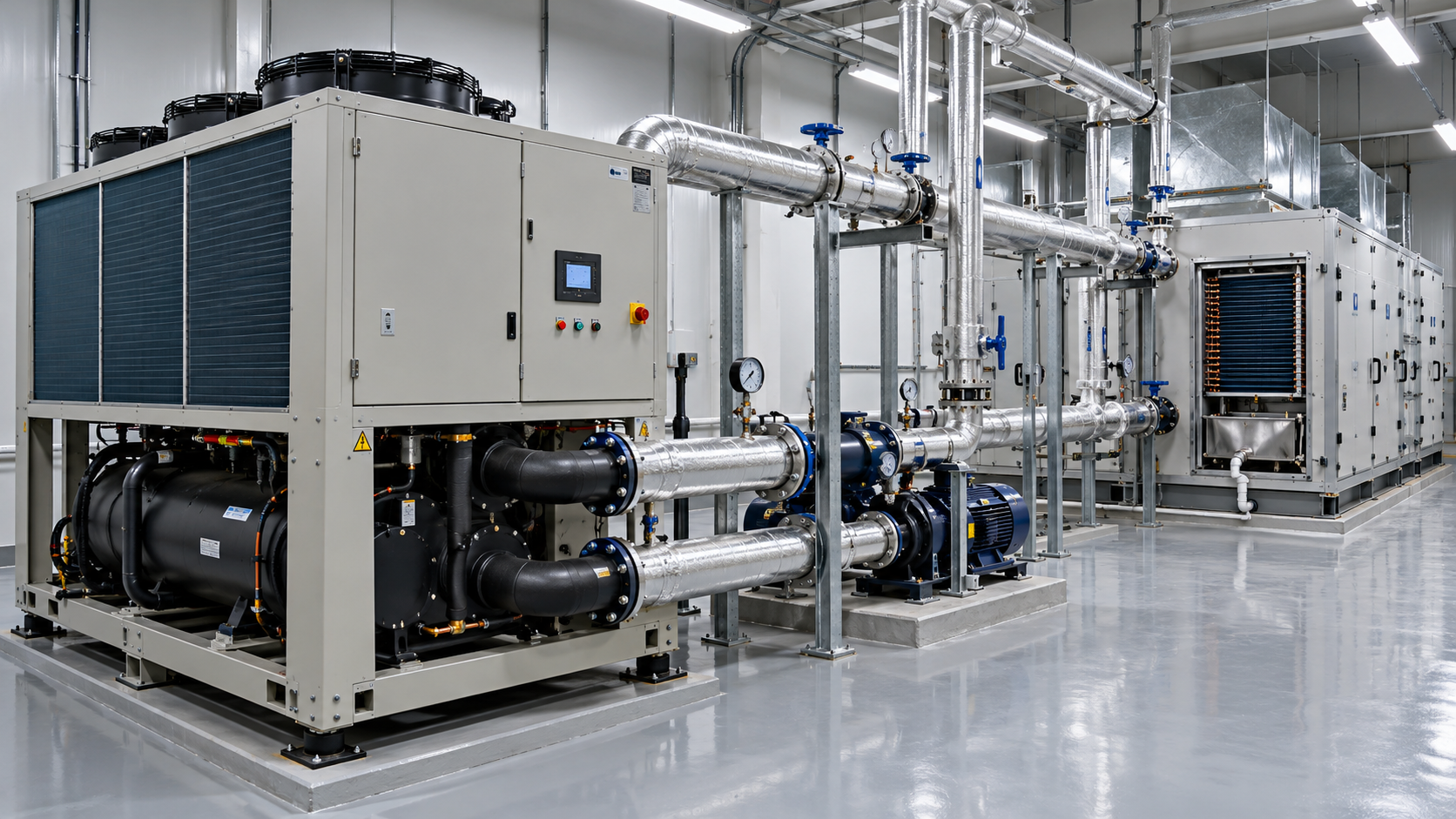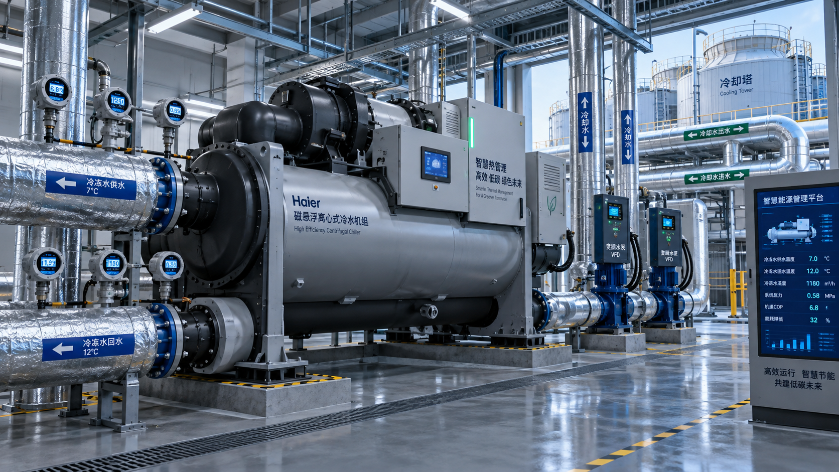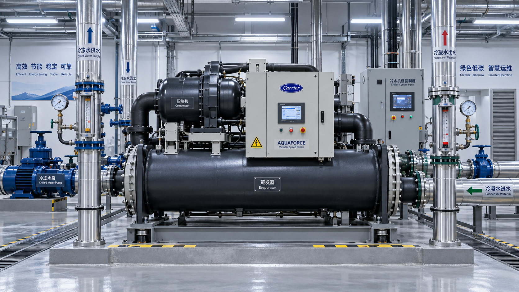




Chiller Optimization Checklist for Rising Energy Use and Unstable Cooling Output




A chiller that suddenly draws more power while delivering uneven cooling rarely fails without leaving clues. The warning signs may be subtle at first: a process temperature that hunts around its setpoint, longer pull-down times after a production change, a condenser approach that keeps widening, or operators reporting that “the chiller runs all the time now.” For after-sales maintenance teams, these symptoms create pressure. Production wants a quick answer, but replacing parts before understanding the operating condition can turn a manageable performance issue into an expensive interruption.
A disciplined chiller optimization checklist helps separate genuine equipment faults from issues caused by load changes, water-side restrictions, poor control sequences, or unsuitable operating conditions. The objective is not simply to lower kW. It is to restore stable heat removal at the lowest practical energy input while protecting the compressor, evaporator, pumps, and downstream process.
The most useful inspections begin with a simple principle: compare what the chiller is doing now with what the system needs it to do. A high electrical reading means little on its own. It must be read alongside cooling load, entering and leaving water temperatures, flow rates, ambient conditions, refrigerant pressures, and operating hours.
Start with the operating picture, not the alarm history
Alarm logs are valuable, but they are only one part of the story. Before touching the refrigerant circuit or changing controller settings, gather a stable operating snapshot. Ideally, take readings after the chiller has operated under a representative load long enough for temperatures and pressures to settle.
- Record chilled-water entering and leaving temperatures, plus the actual temperature differential.
- Measure or verify evaporator and condenser water flow, not just pump status.
- Capture suction and discharge pressures, saturated temperatures, superheat, and subcooling where applicable.
- Note compressor current, voltage balance, run hours, loading position, and capacity-control response.
- Check outdoor ambient temperature for air-cooled units, or cooling-tower approach and condenser-water temperature for water-cooled units.
- Confirm the active setpoint, deadband, reset strategy, schedules, and any building or process control overrides.
This baseline prevents a common maintenance mistake: judging performance against design conditions when the plant is actually operating far away from them. A chiller serving a variable industrial process, for example, may experience a rapid load swing that looks like instability but is actually a control response problem elsewhere in the loop.
If possible, trend the readings rather than relying on a single manual measurement. Fifteen-minute intervals across a full production cycle often reveal short cycling, flow collapse, repeated unloading, or an abnormal condenser temperature rise that a one-time inspection would miss.
Follow the heat path from process to ambient
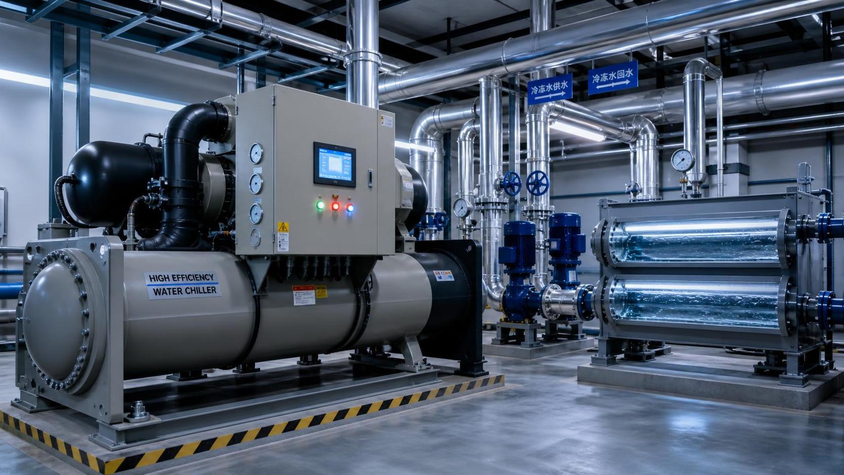
Cooling output becomes unstable when heat cannot move smoothly through the system. Think of the chiller as a chain: heat leaves the process fluid, crosses the evaporator, travels through the refrigerant circuit, and is rejected through the condenser. A restriction, fouled surface, incorrect flow condition, or weak control decision at any point can raise energy use and reduce usable capacity.
1. Check the chilled-water loop for low flow and false temperature signals
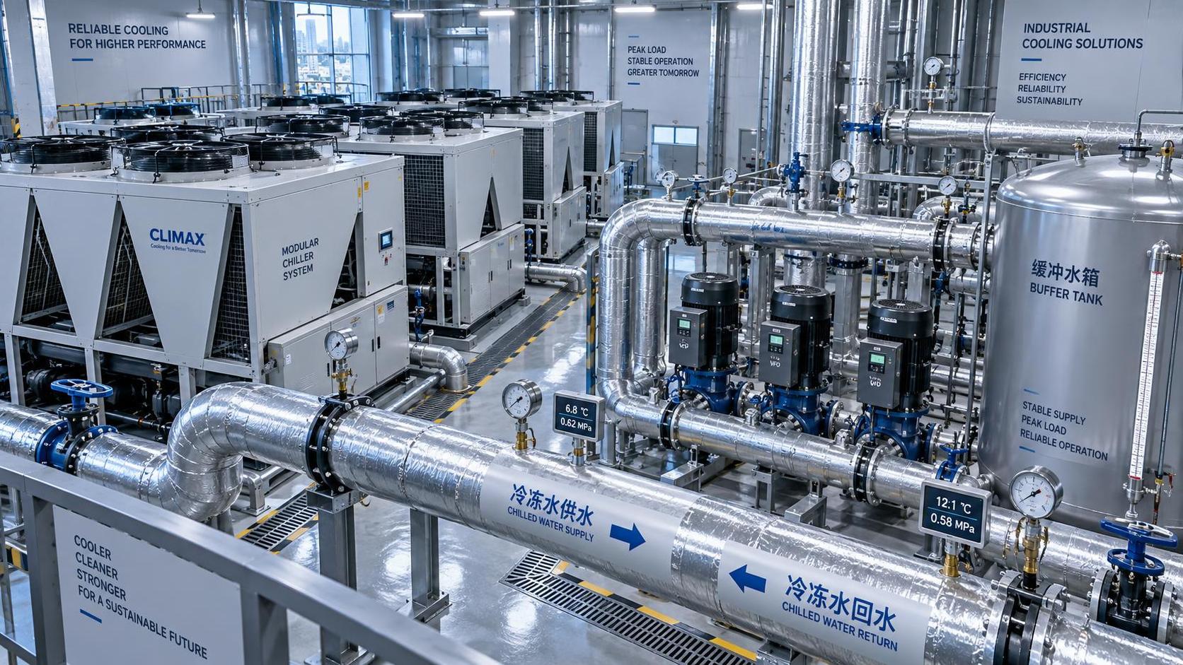
Low evaporator flow is one of the most frequent causes of poor capacity and nuisance trips. It can result from a partially closed valve, dirty strainer, blocked heat exchanger, incorrect variable-speed pump control, air in the circuit, or a bypass arrangement that is sending water around the intended load.
Do not assume a running pump means adequate flow. Compare pump differential pressure with established commissioning values, inspect strainers, and verify that isolation valves are fully positioned. On variable-primary-flow systems, confirm that the pump minimum speed and differential-pressure sensor location allow sufficient flow through the evaporator during low-load conditions.
The chilled-water temperature differential also deserves careful interpretation. A very low differential may indicate excess flow, bypassing, poor coil control, or a load that has fallen away. An unusually high differential can suggest insufficient flow or a heavily loaded process. Neither condition is automatically a chiller fault, but both change how the machine should be expected to perform.
Temperature sensors can quietly undermine an otherwise sound system. A sensor that is offset by even a modest amount may force unnecessary compressor loading or create a misleading diagnosis of inadequate cooling. Compare controller values with calibrated field instruments at the sensor pocket or pipe surface, using proper contact methods and insulation around the probe.
2. Inspect evaporator heat transfer before adjusting refrigerant charge
When leaving chilled-water temperature drifts upward, technicians may be tempted to suspect low refrigerant charge immediately. Yet fouling on the water side, poor flow distribution, or oil-related heat-transfer degradation can create similar symptoms. The key is to evaluate approach temperature: the relationship between leaving chilled-water temperature and refrigerant saturation temperature in the evaporator.
A rising evaporator approach, particularly when flow is verified, points toward reduced heat transfer. For shell-and-tube equipment, review water quality records, tube-cleaning history, and pressure drop across the bundle. For plate heat exchangers, inspect for scaling, debris, or unsuitable glycol concentration. Glycol is often necessary for freeze protection, but excessive concentration increases pumping energy and reduces heat-transfer performance.
Any cleaning decision should match the heat exchanger material, deposit type, and manufacturer guidance. Aggressive chemical treatment without compatibility checks can cause more damage than the original fouling.
3. Treat condenser performance as an energy priority
Many rising-energy complaints begin at the condenser. As condensing temperature increases, the compressor must work against a larger pressure lift. Capacity may fall at the same time, especially during warm weather or high process demand.
For air-cooled chillers, inspect coil cleanliness, fan rotation, fan cycling or variable-speed operation, damaged fins, recirculation of hot discharge air, and clearance around the unit. A coil can look reasonably clean from the outside while holding debris deeper in the fin pack. Clean it with a method that protects fin geometry and electrical components.
For water-cooled systems, verify condenser-water flow and compare entering and leaving temperatures with tower performance. Fouled tubes, scaled strainers, poor tower water treatment, failed basin heaters, fan issues, or a tower bypass valve stuck in the wrong position can all raise head pressure. Check whether the cooling tower is actually responding to load and wet-bulb conditions rather than operating from a fixed, inefficient command.
A practical chiller optimization checklist for the refrigerant circuit
Once water-side conditions are credible, refrigerant-side diagnosis becomes much more meaningful. Maintenance teams should use manufacturer-specific charging and operating guidance, especially on electronic expansion valve systems, low-GWP refrigerants, inverter-driven compressors, and equipment with sophisticated safety logic.
Charging by pressure alone is unreliable. Refrigerant quantity must be judged in the context of system design, load, valve behavior, receiver condition, subcooling, and verified sensor accuracy. Overcharging can push head pressure higher; undercharging may starve the evaporator. Both can appear as “insufficient cooling,” but the corrective action is not the same.
Look carefully for signs of restrictions: a temperature drop across a filter-drier, frosting patterns where they should not occur, or inconsistent liquid-line conditions. Also inspect for leaks using approved methods. Repeatedly adding refrigerant without locating the leak hides the root cause and may create compliance concerns under refrigerant-management rules.
When the compressor is working hard but cooling less
High compressor current is a symptom, not a diagnosis. It may reflect high lift, a heavy process load, mechanical wear, incorrect voltage, poor power quality, or an unsuitable capacity-control sequence. On screw and centrifugal machines, inspect loading behavior and confirm that slide-valve, inlet-guide-vane, or variable-speed control is responding smoothly. A machine forced to operate inefficiently at low load can consume disproportionate energy while producing unstable temperatures.
Electrical checks should include voltage imbalance, loose terminals, contactor condition where fitted, harmonics or drive faults, and motor insulation concerns according to safe maintenance practice. A compressor may remain online while its electrical conditions gradually deteriorate, particularly in plants with frequent starts, variable-frequency drives, or unstable utility supply.
Short cycling deserves immediate attention. Repeated starts shorten component life and often indicate oversized capacity, inadequate system water volume, poor deadband settings, failed staging logic, or a control signal that is fighting another control loop. Adding delay timers without finding the reason for the cycling may only postpone a larger failure.
Controls are often the hidden cause of unstable cooling output
Modern chillers can have capable onboard controllers, but performance depends on how those controllers interact with pumps, cooling towers, process equipment, and supervisory systems. A local setpoint may be correct while an external building management system is repeatedly resetting it. A pump may be commanded to reduce speed before minimum evaporator flow is protected. A tower fan sequence may hold condenser-water temperature unnecessarily high in the name of avoiding frequent cycling.
Review control trends for conflicting commands, rapid setpoint changes, sensor dropout, and manual overrides left in place after an earlier service call. Check that time schedules reflect actual production hours. A chiller running at full readiness through long idle periods may be technically healthy but operationally wasteful.
Setpoint optimization should be conservative and process-led. Raising chilled-water temperature can reduce compressor lift and improve efficiency, but only if product quality, humidity control, equipment temperature limits, and process stability allow it. Small, measured changes with trend review are safer than broad resets made under pressure.
Distinguish a plant-side problem from a chiller-side problem
After-sales teams are often called when the chiller is blamed for poor cooling, yet the actual disturbance may be downstream. A process heat load may have increased because of a new production line, a heat exchanger may be bypassed, control valves may be stuck, or return-water temperature may be distorted by mixing. The most reliable diagnosis uses the energy balance: if flow and temperature differential are known, the cooling load can be estimated and compared with the chiller’s expected operating envelope.
This approach changes the conversation from “the unit is not cold enough” to more useful questions: Has the thermal load changed? Is the chiller seeing the intended flow? Is heat rejection limited? Is the machine being asked to operate beyond the conditions for which it was selected?
Prioritize corrective actions by risk and evidence
Not every finding requires shutdown. A sensible chiller optimization plan separates urgent protection issues from efficiency improvements and longer-term upgrades.
- Act immediately on low-flow conditions, abnormal vibration, repeated safety trips, suspected refrigerant leaks, overheating electrical connections, severe high-head operation, or compressor noise.
- Schedule promptly for coil or tube cleaning, sensor calibration, strainer service, valve repairs, tower maintenance, and control-sequence corrections.
- Plan strategically for variable-speed pump refinements, improved monitoring, water-treatment improvements, heat-recovery evaluation, or replacement decisions where the existing equipment no longer matches the process.
Document the “before” condition and the result after each intervention. Trend kW, cooling output, approach temperatures, flow, run hours, and alarms under similar operating conditions. This record gives service teams evidence for future recommendations and helps site managers see whether a change genuinely improved performance rather than simply shifting the problem.
Make optimization a routine, not an emergency response
The best chiller optimization work happens before comfort complaints, product losses, or production stoppages force a rushed decision. A seasonal review before peak ambient conditions, paired with regular water-side inspections and control-trend checks, can expose performance drift early. For critical applications such as pharmaceutical processing, food production, electronics manufacturing, and precision industrial cooling, that discipline supports both energy control and operational confidence.
GTC-Matrix follows the technologies and operating conditions shaping industrial thermal systems, from heat-exchanger development to compressor efficiency and evolving refrigerant requirements. For maintenance professionals, the enduring lesson is practical: stable cooling is rarely created by one adjustment. It comes from maintaining the full heat-transfer path, verifying control logic, and using measured evidence to guide every service decision.
Ready when you are. Send us a message to get started.
Related News
- How to size a chiller for pharmaceutical cleanroom temperature controlAuthor :Cryogenic Systems Expert

- When do smart thermal systems with sensors reduce chiller energy use?Author :Cryogenic Systems Expert

- Chiller Optimization Checklist for Rising Energy Use and Unstable Cooling OutputAuthor :Cryogenic Systems Expert

- How to Specify a High-Precision Temperature Chiller for Tight-Tolerance ProcessesAuthor :Cryogenic Systems Expert

- Designing Energy-Efficient Industrial Cooling for Variable Process LoadsAuthor :Cryogenic Systems Expert

- Low-GWP Cooling Solutions for Process Plants: Comparing Safety, Efficiency, and CostAuthor :Cryogenic Systems Expert

- How to size energy efficient industrial cooling for a process loadAuthor :Cryogenic Systems Expert

- How to specify high-precision temperature control in EuropeAuthor :Cryogenic Systems Expert

- How cooling system design affects cleanroom contamination controlAuthor :Cryogenic Systems Expert

- When does industrial cooling heat recovery pay back in energy savings?Author :Cryogenic Systems Expert

- How to size an industrial cooling system for peak process loadsAuthor :Cryogenic Systems Expert

- When are aluminum electronics cooling solutions suitable for high-density designs?Author :Cryogenic Systems Expert

- A thermal management guide for preventing chiller capacity lossAuthor :Cryogenic Systems Expert

- When does aluminum make sense for electronics cooling solutions?Author :Cryogenic Systems Expert

- EU Battery Carbon Footprint Labels Become Mandatory on Aug 18 for Battery-Integrated Cooling and Energy Storage ExportsAuthor :Cryogenic Systems Expert

- China-UAE Direct Sea Route Cuts Lead Times for Industrial Cooling and Compression ExportsAuthor :Cryogenic Systems Expert

- EPA Rule Takes Effect for R-410A Equipment ImportsAuthor :Cryogenic Systems Expert

- EN 378-1:2026 Tightens EU Export ChecksAuthor :Cryogenic Systems Expert

- How to Compare Semiconductor Cooling Solutions by Heat Load and Uptime RiskAuthor :Cryogenic Systems Expert

- EU Label Deadline Hits China Chiller ExportsAuthor :Cryogenic Systems Expert

- How Smart Thermal Systems Improve Industrial Cooling EfficiencyAuthor :Cryogenic Systems Expert

- How to Choose Process Cooling Equipment for Stable Temperature ControlAuthor :Cryogenic Systems Expert

- EU Finalizes 2026 HFC Quota Cut for R-134a ChillersAuthor :Cryogenic Systems Expert

- EU Tightens HFC-134a Quotas for Industrial ChillersAuthor :Cryogenic Systems Expert

- REACH SVHC Update Pressures HFC-134a Chiller Supply ChainsAuthor :Cryogenic Systems Expert

- EU PFAS Coolant Ban Reshapes Chiller ExportsAuthor :Cryogenic Systems Expert

- EU REACH Restricts PFAS Cooling Media ImportsAuthor :Cryogenic Systems Expert

- EU Ecodesign Rule Takes Effect for Industrial ChillersAuthor :Cryogenic Systems Expert

- EU REACH Rule Takes Effect for PFAS in Industrial Cooling ExportsAuthor :Cryogenic Systems Expert

- Industrial Cooling for Plastic Processing: How to Size for Stable Cycle TimesAuthor :Cryogenic Systems Expert

- EU F-Gas Update Bars R404A/R507 in Commercial CoolingAuthor :Cryogenic Systems Expert

- DOE Raises Chiller Efficiency Standard From October 2026Author :Cryogenic Systems Expert

- India Mandates BIS Energy Certification for Industrial ChillersAuthor :Cryogenic Systems Expert

- Energy-Efficient Heat Exchange for Process Cooling: Cost vs PaybackAuthor :Cryogenic Systems Expert

- EPA R-134a Import Ban Takes Effect on July 13, 2026Author :Cryogenic Systems Expert

- India BIS Rule Takes Effect for Industrial ChillersAuthor :Cryogenic Systems Expert