How to size an industrial cooling system for peak process loads




Peak-load sizing is where industrial cooling projects either gain resilience or inherit a permanent operating problem. A system sized to average heat rejection can appear adequate during steady production, then lose temperature control during startup, cleaning cycles, high-throughput batches, summer ambient conditions, or simultaneous equipment operation. The result is not simply warmer water: it can mean unstable product quality, alarms, reduced machine output, shortened component life, or unplanned reliance on temporary cooling.
The required capacity of an industrial cooling system should therefore be based on a defined worst credible operating condition, not on nameplate equipment totals and not on historical average utility consumption. The central task is to build a heat-load model that separates continuous process duty, intermittent peaks, environmental gains, and contingency requirements—then verify that the selected configuration can deliver that duty at the actual leaving-fluid temperature and heat-rejection conditions.
Start with the process condition that must be protected
Cooling capacity is meaningful only when connected to a process requirement. Before calculating tons or kilowatts, define the operating envelope that cannot be compromised:
- Required supply-fluid temperature and allowable deviation at each critical load;
- Required return-fluid temperature under full production;
- Process fluid composition, including glycol concentration, corrosion inhibitors, water quality, or dielectric fluid requirements;
- Minimum and maximum flow at the process interface;
- Operating profiles: continuous operation, batch cycles, shift changes, clean-in-place phases, and equipment startup;
- Design ambient conditions for the site and the expected mode of heat rejection;
- Availability target, including whether loss of one cooling module is acceptable.
A common error is to define the system around a nominal “chilled water temperature” without establishing the permitted temperature rise across each process load. A laser, extrusion die, fermentation vessel, hydraulic power unit, vacuum pump, or reactor jacket may all be connected to the same loop but have very different consequences when supply temperature rises by several degrees. The most temperature-sensitive duty should influence the hydraulic arrangement and control philosophy, even if it is not the largest source of heat.
It is also important to distinguish between a process that requires low supply temperature and one that requires tight temperature stability. A process with a wide acceptable temperature band may tolerate a higher leaving-water setpoint and benefit from efficient economizer or free-cooling operation. A process requiring narrow control may need buffer volume, variable-speed capacity control, secondary pumping, or a dedicated loop rather than a larger central chiller alone.
Build the load from heat sources, not from a single utility meter
The total peak cooling requirement is the sum of heat entering the cooling fluid during the selected operating scenario. Depending on the process, this may include heat generated directly by equipment, material heat removal, heat transfer through vessels or piping, and parasitic loads from the surrounding environment.
For a liquid loop, the most useful field calculation is:
Q = ṁ × Cp × ΔT
Where Q is cooling duty, ṁ is mass flow rate, Cp is the fluid’s specific heat capacity, and ΔT is the measured or specified temperature rise. In practical water-based systems, this can be converted using volumetric flow and fluid properties at the actual glycol concentration and operating temperature. Water-only assumptions become inaccurate when glycol concentration is significant: glycol reduces specific heat and changes viscosity, which affects both capacity calculations and pump selection.
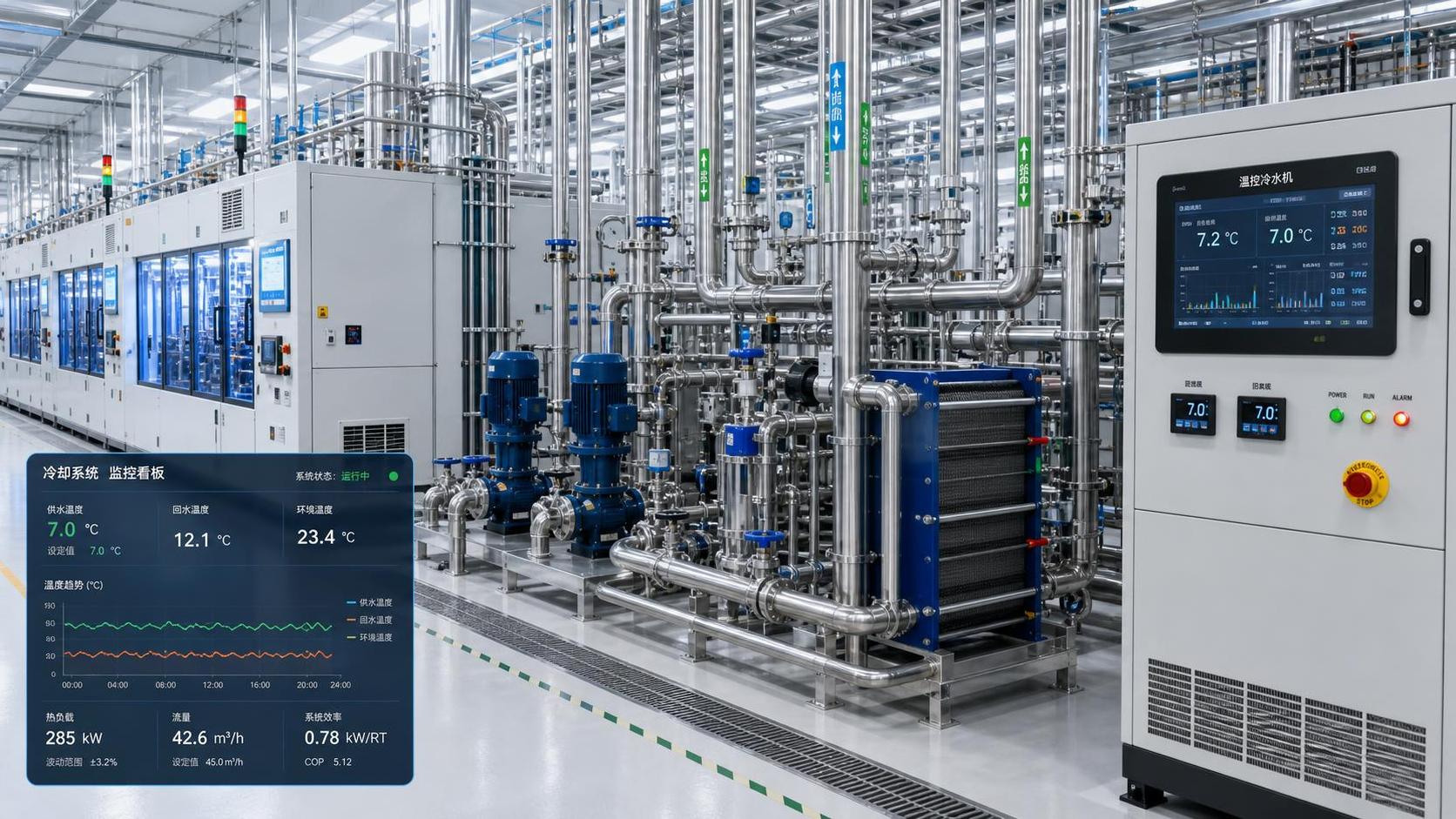
Measured flow and temperature data are often more reliable than an equipment nameplate, provided they are captured during a representative high-load period and instruments are credible. The temperature sensors should be placed where they measure the process loop rather than a mixed header, bypass stream, or poorly insulated section of pipe. A small temperature measurement error becomes material when flow is high and the loop delta-T is low.
Where direct measurement is not available, the heat inventory should include the following sources as applicable:
- Electrical and mechanical losses. Motor, drive, hydraulic, compressor, and power-electronics losses often emerge as heat in the equipment room or directly into a cooling circuit. Input power is not automatically equal to cooling load; the fraction rejected to the fluid must be identified.
- Product or material cooling. Solids, liquids, molds, or reaction products may require sensible cooling, phase-change removal, or both. Batch mass, initial and final temperatures, specific heat, cycle duration, and simultaneous batches determine the peak.
- Reaction and process heat. Exothermic chemical, biological, or mixing processes require a process-energy balance, not a generic equipment factor. The peak reaction rate may be brief yet decisive for equipment capacity.
- Heat gain from ambient. Open tanks, uninsulated piping, hot production spaces, solar-exposed outdoor lines, and infiltration into conditioned enclosures can add load. These gains are particularly relevant when process temperatures are below ambient.
- Connected auxiliary loads. Control cabinets, vacuum systems, test stands, compressors, condensers, and heat exchangers can be overlooked when they share a loop or enter operation during peak production.
For batch processes, energy and instantaneous duty must be considered separately. Removing a given number of kilowatt-hours over two hours requires a very different chiller capacity than removing the same energy in twenty minutes. A system may have enough daily cooling energy but insufficient instantaneous capacity to prevent a batch temperature excursion.
Define “peak” as a credible coincident event
Adding every connected load at its maximum nameplate duty produces a conservative figure, but it can also create unnecessary capital cost, poor part-load performance, and oversized pumps, pipes, and electrical infrastructure. The alternative is not to apply an arbitrary diversity factor. It is to establish which loads genuinely overlap under the operating condition the facility needs to sustain.
A peak-load schedule should map each significant load against time. It should show startup, production, regeneration, defrost, cleaning, material charging, and other intermittent events. This exposes whether the largest loads occur together, whether they are sequenced by control logic, and whether an operator can reasonably defer a noncritical load during an upset.
Coincidence assumptions deserve explicit documentation. If two machines are assumed not to run together, that assumption should be enforceable by production scheduling or an interlock—not merely based on normal habit. If a new product recipe or a future second shift could remove that diversity, the installed cooling system may become undersized without any equipment failure.
Different peak definitions may be needed for different purposes. The highest process heat load determines evaporator-side capacity. The highest outdoor wet-bulb or dry-bulb condition affects condenser-side performance. The highest simultaneous electrical demand may occur in a different hour. Treating these as one generic “design day” can hide important constraints.
Convert the process load into equipment capacity at real conditions
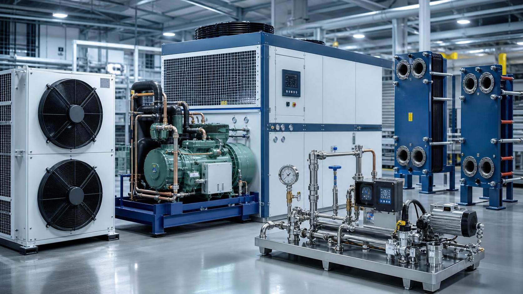
Chiller capacity is not a fixed number independent of conditions. Catalog capacity is quoted at stated leaving-fluid temperature, entering-fluid temperature, flow rate, ambient condition, and often a particular fouling condition. A unit rated at one condition can provide materially less capacity when asked to produce colder glycol, reject heat into hotter outdoor air, or operate with reduced heat-exchanger flow.
For air-cooled chillers, the critical heat-rejection condition is normally outdoor dry-bulb temperature. For evaporative systems and cooling towers, entering-air wet-bulb temperature is central. Water-cooled chillers also depend on the condenser-water temperature supplied by the tower, the selected approach temperature, and the tower’s ability to perform at the design wet bulb. The cooling system selection should use manufacturer performance data at the specified conditions rather than a nominal rating from a preliminary datasheet.
Low-temperature loops require additional caution. Glycol concentration protects against freezing but reduces heat transfer and raises pressure drop. As evaporating temperature falls, compressor lift rises and capacity declines while power demand increases. A process setpoint that is lower than necessary can therefore create a compounding penalty in chiller size, pumping energy, and annual operating cost.
The heat-rejection device must also be sized for more than the process load. A refrigeration chiller rejects the absorbed process heat plus compressor power and other losses. Therefore, the condenser, dry cooler, cooling tower, and associated airflow or water flow must accommodate a heat-rejection load greater than the evaporator cooling duty. This distinction is frequently missed when a process-load figure is passed directly to a condenser-side design team.
Reserve capacity is not the same as a generic safety factor
Some margin is appropriate because calculated loads, ambient conditions, fouling rates, and future operating modes all contain uncertainty. But a blanket percentage added at the end of the calculation is a weak substitute for understanding where uncertainty originates.
Separate the reasons for additional capacity:
- Measurement and modeling uncertainty: incomplete heat-source data, uncertain cycle timing, or conservative assumptions in a new process;
- Performance degradation: heat-exchanger fouling, reduced airflow, scaling, or changes in fluid condition;
- Expansion allowance: defined future equipment or production throughput, with a known load estimate and implementation horizon;
- Availability allowance: ability to meet a stated duty after one chiller, pump, fan group, or electrical feeder is unavailable.
These needs lead to different design choices. A future expansion allowance may justify space, valved connections, electrical provisions, and hydraulic headers for an additional module rather than purchasing all capacity on day one. A high availability requirement may favor multiple chillers with independent circuits, staged controls, and N+1 capacity. Adding one oversized machine does not provide redundancy if its compressor, controller, evaporator, or electrical supply becomes the single point of failure.
Modular capacity can also improve part-load operation, but only if the modules can stage efficiently and maintain required flow. Poor sequencing can leave several compressors lightly loaded, create excessive cycling, or operate pumps at fixed high speed when demand is low. Capacity redundancy and control quality must be evaluated together.
Check the hydraulic system before approving the thermal design
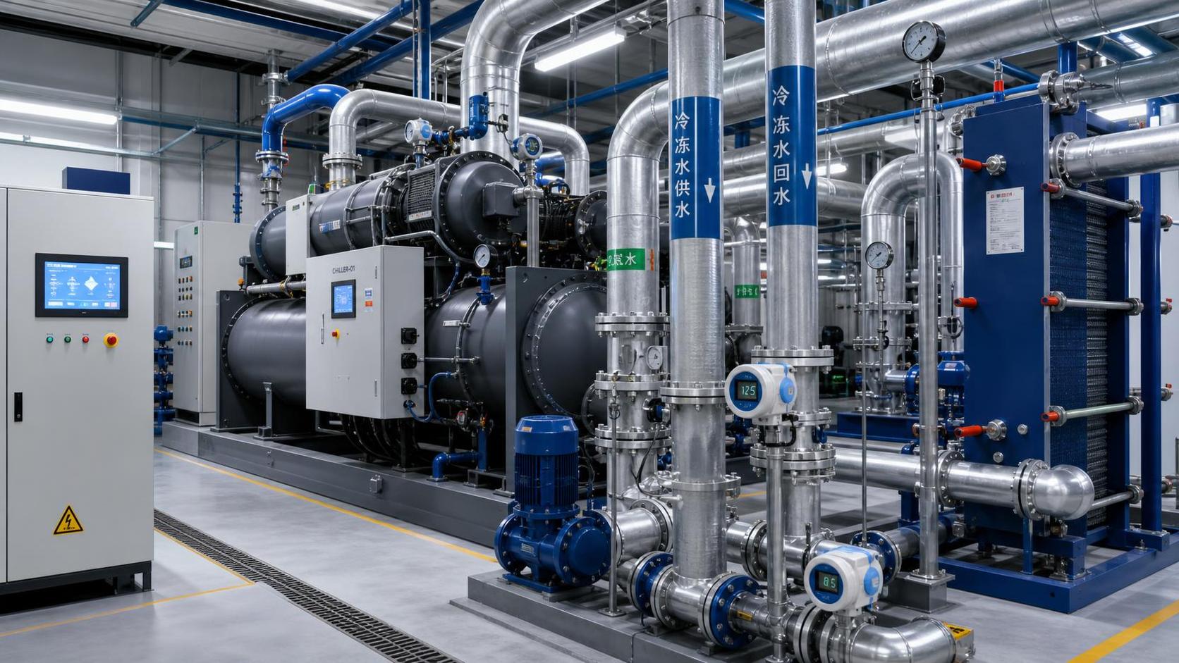
A correctly sized chiller can still fail to deliver stable process cooling if the hydraulic design is weak. The loop must carry the calculated duty at a practical delta-T while meeting the pressure-drop requirements of heat exchangers, filters, control valves, hoses, and distribution piping.
Very low delta-T designs increase flow substantially. That raises pipe size, pump power, valve authority concerns, and the sensitivity of calculated capacity to sensor error. Excessively high delta-T, however, may leave insufficient flow through equipment or cause unacceptable surface temperatures. The selected delta-T should reflect the process equipment’s heat-transfer design, not just a preference for a smaller or larger pump.
Variable-flow systems need special attention where chillers, evaporators, or process equipment require a minimum flow. A decoupled primary-secondary arrangement, a controlled bypass, or variable-primary-flow controls may be appropriate depending on the equipment and operating range. The decision should be based on the manufacturer’s flow limits and on a hydraulic model of the actual network, including partially closed control valves and future branches.
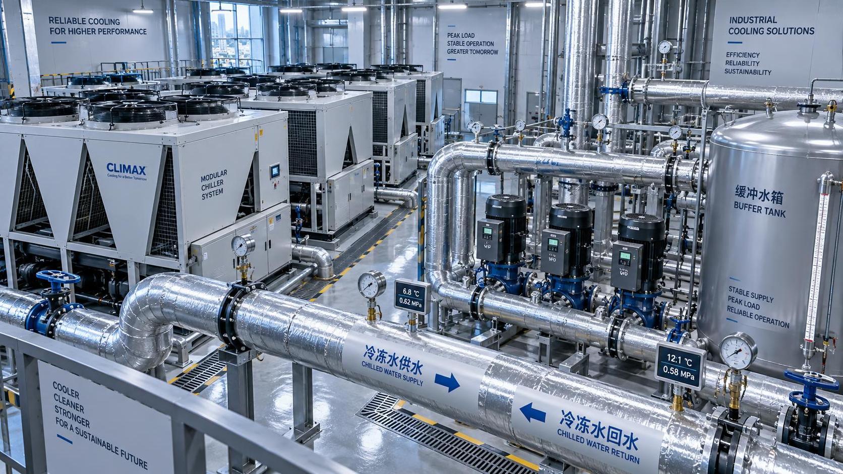
Buffer tanks serve a specific purpose: they add thermal mass, reduce short cycling, absorb short-duration load changes, and separate rapid process fluctuations from chiller capacity control. They do not create refrigeration capacity. If a peak lasts longer than the usable stored energy, the chiller still has to carry the sustained load. Tank sizing should be based on allowable temperature drift, minimum equipment run time, loop volume, and the duration of the transient event.
Compare configurations by the constraint they solve
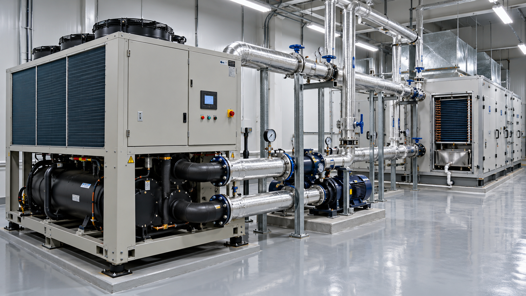
Air-cooled chillers avoid cooling-water treatment and tower infrastructure, but their peak capacity and efficiency are exposed to high outdoor dry-bulb temperatures. Water-cooled chillers can offer favorable performance where a cooling tower and water-management program are acceptable, yet their practical capacity depends on wet-bulb conditions and condenser-water quality. Dry coolers and fluid coolers can be effective where process supply temperatures are high enough to approach ambient conditions, especially when an economizer mode can operate without mechanical refrigeration for part of the year.
A central system is not automatically preferable to distributed chillers. Centralization can simplify maintenance, create useful load diversity, and support phased expansion. Distributed equipment can isolate incompatible fluids, prevent a plant-wide outage from affecting every process, and reduce long distribution runs. The deciding question is whether the loads share compatible temperature, fluid-quality, availability, and operating-hour requirements.
Where a critical low-temperature process shares infrastructure with a high-temperature machine-cooling load, separate loops connected by a heat exchanger may be more robust than forcing one temperature level onto all users. The lower-temperature loop should not be selected merely because it can serve every load; it should be justified by the actual process requirement.
Use lifecycle checks to challenge a seemingly adequate selection
Before release, the selected system should be tested against a small number of explicit scenarios: full coincident process load at design ambient; expected production load at typical ambient; minimum load; startup after a warm shutdown; loss of the largest cooling module; and the defined future expansion condition. Each scenario should check supply temperature, available capacity, flow, pump head, electrical demand, and control response.
Factory performance data should be reconciled with the project schedule of conditions, including fluid type, fouling allowances, altitude where relevant, and condenser-side design temperatures. Acceptance testing should verify the same basis. Comparing site performance with a rating measured at unrelated conditions can lead to false conclusions about either chiller underperformance or process overload.
Energy evaluation should focus on the load profile rather than full-load efficiency alone. A cooling plant spends much of its operating time away from its maximum design duty. Compressor unloading behavior, fan control, pump turndown, condenser-water reset, free-cooling availability, and required supply-temperature stability may have greater annual impact than a small difference in nominal peak efficiency. Lower pressure drop and higher permissible process temperatures can reduce energy use without sacrificing process protection.
The final capacity number should be traceable: every load contribution, coincidence assumption, ambient condition, reserve requirement, and manufacturer correction should be visible in the calculation record. That traceability is what makes an industrial cooling system defensible when production changes, equipment is added, or a summer performance problem has to be diagnosed. Peak sizing is not a single capacity estimate; it is a verified operating case that the thermal plant must sustain.
Ready when you are. Send us a message to get started.
Related News
- How to size a chiller for pharmaceutical cleanroom temperature controlAuthor :Cryogenic Systems Expert

- When do smart thermal systems with sensors reduce chiller energy use?Author :Cryogenic Systems Expert

- Chiller Optimization Checklist for Rising Energy Use and Unstable Cooling OutputAuthor :Cryogenic Systems Expert

- How to Specify a High-Precision Temperature Chiller for Tight-Tolerance ProcessesAuthor :Cryogenic Systems Expert

- Designing Energy-Efficient Industrial Cooling for Variable Process LoadsAuthor :Cryogenic Systems Expert

- Low-GWP Cooling Solutions for Process Plants: Comparing Safety, Efficiency, and CostAuthor :Cryogenic Systems Expert

- How to size energy efficient industrial cooling for a process loadAuthor :Cryogenic Systems Expert

- How to specify high-precision temperature control in EuropeAuthor :Cryogenic Systems Expert

- How cooling system design affects cleanroom contamination controlAuthor :Cryogenic Systems Expert

- When does industrial cooling heat recovery pay back in energy savings?Author :Cryogenic Systems Expert

- How to size an industrial cooling system for peak process loadsAuthor :Cryogenic Systems Expert

- When are aluminum electronics cooling solutions suitable for high-density designs?Author :Cryogenic Systems Expert

- A thermal management guide for preventing chiller capacity lossAuthor :Cryogenic Systems Expert

- When does aluminum make sense for electronics cooling solutions?Author :Cryogenic Systems Expert

- EU Battery Carbon Footprint Labels Become Mandatory on Aug 18 for Battery-Integrated Cooling and Energy Storage ExportsAuthor :Cryogenic Systems Expert

- China-UAE Direct Sea Route Cuts Lead Times for Industrial Cooling and Compression ExportsAuthor :Cryogenic Systems Expert

- EPA Rule Takes Effect for R-410A Equipment ImportsAuthor :Cryogenic Systems Expert

- EN 378-1:2026 Tightens EU Export ChecksAuthor :Cryogenic Systems Expert

- How to Compare Semiconductor Cooling Solutions by Heat Load and Uptime RiskAuthor :Cryogenic Systems Expert

- EU Label Deadline Hits China Chiller ExportsAuthor :Cryogenic Systems Expert

- How Smart Thermal Systems Improve Industrial Cooling EfficiencyAuthor :Cryogenic Systems Expert

- How to Choose Process Cooling Equipment for Stable Temperature ControlAuthor :Cryogenic Systems Expert

- EU Finalizes 2026 HFC Quota Cut for R-134a ChillersAuthor :Cryogenic Systems Expert

- EU Tightens HFC-134a Quotas for Industrial ChillersAuthor :Cryogenic Systems Expert

- REACH SVHC Update Pressures HFC-134a Chiller Supply ChainsAuthor :Cryogenic Systems Expert

- EU PFAS Coolant Ban Reshapes Chiller ExportsAuthor :Cryogenic Systems Expert

- EU REACH Restricts PFAS Cooling Media ImportsAuthor :Cryogenic Systems Expert

- EU Ecodesign Rule Takes Effect for Industrial ChillersAuthor :Cryogenic Systems Expert

- EU REACH Rule Takes Effect for PFAS in Industrial Cooling ExportsAuthor :Cryogenic Systems Expert

- Industrial Cooling for Plastic Processing: How to Size for Stable Cycle TimesAuthor :Cryogenic Systems Expert

- EU F-Gas Update Bars R404A/R507 in Commercial CoolingAuthor :Cryogenic Systems Expert

- DOE Raises Chiller Efficiency Standard From October 2026Author :Cryogenic Systems Expert

- India Mandates BIS Energy Certification for Industrial ChillersAuthor :Cryogenic Systems Expert

- Energy-Efficient Heat Exchange for Process Cooling: Cost vs PaybackAuthor :Cryogenic Systems Expert

- EPA R-134a Import Ban Takes Effect on July 13, 2026Author :Cryogenic Systems Expert

- India BIS Rule Takes Effect for Industrial ChillersAuthor :Cryogenic Systems Expert