


How to size a high-efficiency industrial cooling chiller




Size an industrial chiller around the cooling load it must remove under defined operating conditions, then check how efficiently it will serve the same process at partial load. A capacity rating on its own cannot tell you whether the unit will maintain temperature during the hottest production period or operate efficiently during quieter shifts.
For high efficiency industrial cooling, the practical target is a chiller that meets the coincident peak load with a justified allowance, while retaining stable control across the range of loads expected in normal operation. Start with process heat, translate it into a design duty at the required temperatures, and compare equipment using the same operating conditions and boundaries.
Build the load from the process, not the equipment nameplate
The design cooling load is the rate at which heat must be removed to maintain the required process conditions. Depending on the application, it can include heat generated by machinery, heat brought in by a warm product, heat entering through tanks and pipework, and heat added by pumps. A batch process may also require cooling a vessel or product from one temperature to another within a specified time.
Electrical input can be useful evidence, but it is not automatically equal to the cooling load. Some energy may leave with the product, exhaust air, mechanical work or other heat sinks. Equally, a cooling circuit may receive heat from several sources beyond the main machine. Use measured heat transfer where possible, and document assumptions where measurements are unavailable.
For an existing liquid-cooling circuit operating at reasonably steady conditions, estimate the heat removed using:
Cooling load (kW) = mass flow rate (kg/s) × specific heat capacity (kJ/kg·K) × return-to-supply temperature difference (K)
For water, an approximate calculation using volume flow is:
Cooling load (kW) ≈ 1.16 × water flow rate (m³/h) × temperature difference (°C)
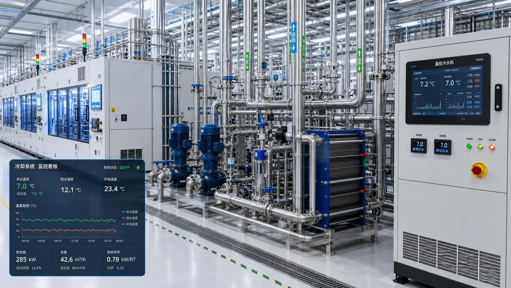
As an illustration, water flowing at 10 m³/h and warming from 7°C at supply to 12°C at return carries approximately 58 kW of heat. This is the load at the measurement point and operating moment; it does not prove that 58 kW is the site’s maximum requirement.
Flow and temperature readings should represent the same period. Record them during relevant production states, including startup, sustained production and any known high-load cycle. If flow varies, calculate load from paired flow and temperature measurements over time rather than combining an unrelated maximum flow and maximum temperature difference.
For glycol mixtures or other fluids, use the fluid’s actual density and specific heat at the relevant concentration and temperature. The water shortcut can misstate duty, while viscosity and freezing behavior can also affect pump selection, heat transfer and minimum operating temperature.
Find the coincident peak and the load range
Adding the maximum cooling demand of every machine can substantially overstate the capacity needed when those machines do not peak together. Map the production schedule and identify which loads can realistically occur at the same time. Conversely, do not apply a diversity assumption merely because equipment is installed in different areas: a shared startup or production changeover can bring several loads online together.
For batch cooling, calculate the energy to be removed and divide it by the available cooling time. A simple estimate for a liquid batch is mass multiplied by specific heat and the required temperature reduction. Add heat entering during the cooling period and any vessel or equipment mass that must also be cooled. The average duty over the batch is a starting point; the instantaneous duty and achievable cooling rate depend on heat exchanger performance and the changing temperature difference.
Next, establish the minimum and typical loads as well as the peak. A chiller selected for a short daily peak may spend most of its operating hours at a small fraction of rated capacity. That profile influences compressor staging, variable-speed control, buffer volume and the potential value of multiple chillers.
Apply a margin only after identifying what it covers: measurement uncertainty, an expected production increase, heat gains not yet measured, or another defined risk. Stacking several unexplained safety factors can produce an oversized machine that cycles frequently and costs more to operate. Planned future expansion is better assessed as a separate scenario, especially if its timing or scale is uncertain.
Specify the temperatures and site conditions behind the capacity
Chiller capacity changes with operating conditions. A quoted capacity is useful only when the rating conditions are close enough to the intended duty, or when the manufacturer has recalculated performance for the actual specification. Ask for selections at the design chilled-fluid temperatures and the relevant condenser conditions.
The following inputs should accompany the required cooling capacity:
- Supply temperature and allowable variation: Define the temperature needed at the process, including tolerance and any distribution losses between chiller and equipment.
- Return temperature and flow: State the expected design flow and temperature rise, along with the normal operating range. The selected evaporator must support the required flow and pressure drop.
- Fluid composition: Identify water treatment or glycol type and concentration. These affect thermal properties, pressure drop and freeze protection.
- Condenser conditions: For an air-cooled unit, specify the design ambient temperature and installation constraints. For a water-cooled unit, specify condenser-water temperatures, available flow and the cooling-water system.
- Operating profile: Describe annual or representative hours at different loads and ambient conditions, including shutdowns and low-load periods.
Lowering chilled-water supply temperature may improve a process margin, but it generally increases the temperature lift the refrigeration system must provide and can reduce efficiency and available capacity. Set the supply temperature as high as the process can reliably accept, allowing for control tolerance and distribution losses. Check individual process equipment limits before changing an existing setpoint.
Ambient conditions deserve equal care. An air-cooled chiller may deliver less capacity when outdoor air is hotter, precisely when some facilities have their highest heat load. The design ambient should reflect the site and required reliability, not just a convenient catalog condition. Also review airflow clearance and the possibility of hot discharge air recirculating into the condenser intake.
Compare efficiency over operating hours
Two chillers with the same design capacity can have different annual energy use. The better choice depends on how the units perform across the actual load and temperature profile, including minimum stable output and the energy used by supporting equipment.
Request power and cooling output at the design point and at representative part-load points. Compare coefficient of performance or input power under equivalent conditions, and check which components are included. A compressor-only figure should not be compared directly with a package figure that includes fans, pumps or controls. For a water-cooled option, account for cooling-tower fans, condenser-water pumps and water-related operating costs within the chosen system boundary.
A simple annual comparison can be built by dividing operation into representative bins. For each bin, multiply the expected hours by the corresponding total system power, then add the results. Include periods when production is idle but pumps or controls remain energized. The result is an estimate, so its usefulness depends on the quality of the load and ambient assumptions.
Variable-speed equipment can offer strong part-load performance, but a drive does not guarantee the lowest system energy use. Minimum compressor speed, control strategy, pump arrangement, condenser conditions and cycling behavior all matter. Likewise, a high full-load efficiency figure does not establish how a unit will perform through long periods of light production.
Check control stability and resilience before fixing the configuration
Oversizing can create a control problem even when the chiller has enough nominal capacity. If minimum output exceeds the process load, the compressor may cycle or the supply temperature may fluctuate. Ask the manufacturer for the minimum continuous capacity and permitted cycling behavior at the specified conditions, then compare those limits with the lowest sustained process load.
A buffer tank can add thermal mass and reduce rapid cycling, but it does not eliminate an unsuitable capacity range. Its useful size depends on fluid volume, allowable temperature swing, load changes and the control scheme. For rapidly varying processes, assess whether the process can tolerate that temperature swing and whether the chiller can respond quickly enough.
Multiple smaller chillers may provide a better match to a variable load and permit maintenance without a complete shutdown. They also add equipment, controls and potentially pump energy. A standby arrangement should be sized against the actual continuity requirement: determine whether the site needs full production during a failure or only enough capacity to protect critical processes.
Finally, compare lifecycle cost using the same duty and scope for each option. Include installed equipment, electrical and pipework modifications, expected energy use, maintenance, and the operational consequence of a cooling interruption. The selected capacity should be traceable to a documented load profile and a performance calculation at site conditions; that record gives the evaluator a basis for challenging both an undersized bid and an unnecessarily large one.
Ready when you are. Send us a message to get started.
Related News
- How to size a high-efficiency industrial cooling chillerAuthor :Cryogenic Systems Expert

- How to size a chiller for pharmaceutical cleanroom temperature controlAuthor :Cryogenic Systems Expert

- When do smart thermal systems with sensors reduce chiller energy use?Author :Cryogenic Systems Expert

- Chiller Optimization Checklist for Rising Energy Use and Unstable Cooling OutputAuthor :Cryogenic Systems Expert

- How to Specify a High-Precision Temperature Chiller for Tight-Tolerance ProcessesAuthor :Cryogenic Systems Expert

- Designing Energy-Efficient Industrial Cooling for Variable Process LoadsAuthor :Cryogenic Systems Expert

- Low-GWP Cooling Solutions for Process Plants: Comparing Safety, Efficiency, and CostAuthor :Cryogenic Systems Expert

- How to size energy efficient industrial cooling for a process loadAuthor :Cryogenic Systems Expert

- How to specify high-precision temperature control in EuropeAuthor :Cryogenic Systems Expert

- How cooling system design affects cleanroom contamination controlAuthor :Cryogenic Systems Expert

- When does industrial cooling heat recovery pay back in energy savings?Author :Cryogenic Systems Expert

- How to size an industrial cooling system for peak process loadsAuthor :Cryogenic Systems Expert

- When are aluminum electronics cooling solutions suitable for high-density designs?Author :Cryogenic Systems Expert

- A thermal management guide for preventing chiller capacity lossAuthor :Cryogenic Systems Expert

- When does aluminum make sense for electronics cooling solutions?Author :Cryogenic Systems Expert

- EU Battery Carbon Footprint Labels Become Mandatory on Aug 18 for Battery-Integrated Cooling and Energy Storage ExportsAuthor :Cryogenic Systems Expert

- China-UAE Direct Sea Route Cuts Lead Times for Industrial Cooling and Compression ExportsAuthor :Cryogenic Systems Expert

- EPA Rule Takes Effect for R-410A Equipment ImportsAuthor :Cryogenic Systems Expert

- EN 378-1:2026 Tightens EU Export ChecksAuthor :Cryogenic Systems Expert

- How to Compare Semiconductor Cooling Solutions by Heat Load and Uptime RiskAuthor :Cryogenic Systems Expert

- EU Label Deadline Hits China Chiller ExportsAuthor :Cryogenic Systems Expert

- How Smart Thermal Systems Improve Industrial Cooling EfficiencyAuthor :Cryogenic Systems Expert

- How to Choose Process Cooling Equipment for Stable Temperature ControlAuthor :Cryogenic Systems Expert

- EU Finalizes 2026 HFC Quota Cut for R-134a ChillersAuthor :Cryogenic Systems Expert

- EU Tightens HFC-134a Quotas for Industrial ChillersAuthor :Cryogenic Systems Expert

- REACH SVHC Update Pressures HFC-134a Chiller Supply ChainsAuthor :Cryogenic Systems Expert

- EU PFAS Coolant Ban Reshapes Chiller ExportsAuthor :Cryogenic Systems Expert

- EU REACH Restricts PFAS Cooling Media ImportsAuthor :Cryogenic Systems Expert

- EU Ecodesign Rule Takes Effect for Industrial ChillersAuthor :Cryogenic Systems Expert

- EU REACH Rule Takes Effect for PFAS in Industrial Cooling ExportsAuthor :Cryogenic Systems Expert

- Industrial Cooling for Plastic Processing: How to Size for Stable Cycle TimesAuthor :Cryogenic Systems Expert

- EU F-Gas Update Bars R404A/R507 in Commercial CoolingAuthor :Cryogenic Systems Expert

- DOE Raises Chiller Efficiency Standard From October 2026Author :Cryogenic Systems Expert

- India Mandates BIS Energy Certification for Industrial ChillersAuthor :Cryogenic Systems Expert

- Energy-Efficient Heat Exchange for Process Cooling: Cost vs PaybackAuthor :Cryogenic Systems Expert

- EPA R-134a Import Ban Takes Effect on July 13, 2026Author :Cryogenic Systems Expert