



How to size energy efficient industrial cooling for a process load




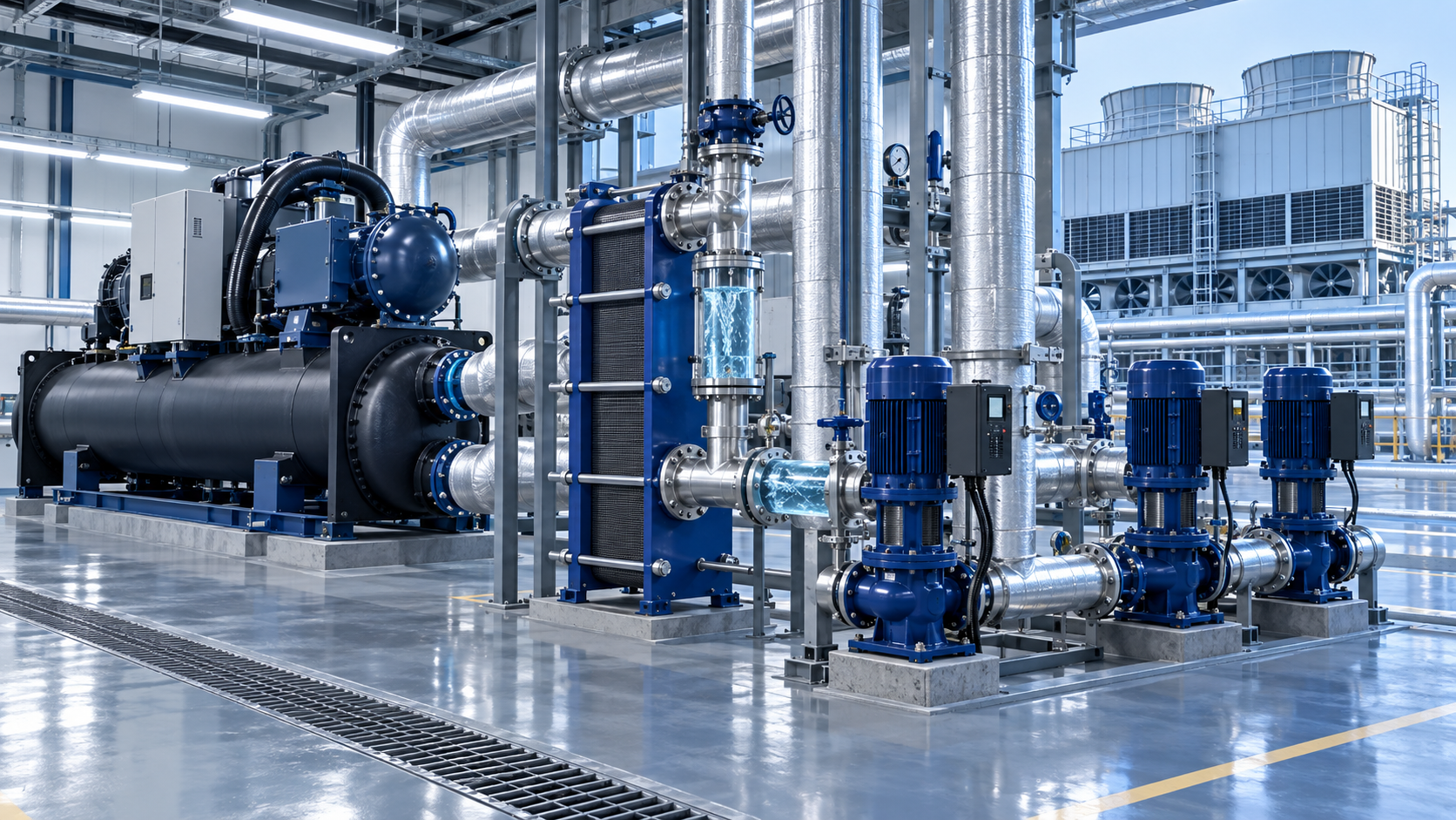
Start with the heat that must be removed at the process boundary, then size the cooling system around the full operating envelope rather than a single peak value. A chiller, cooling tower, dry cooler, pump skid, or heat exchanger that matches a nameplate load only at one condition can be oversized during normal production, undersized during summer operation, or unable to hold the required supply temperature when the process changes state.
For energy efficient industrial cooling, the design basis should show three things clearly: how heat enters the coolant, how the load varies over time, and what conditions the heat-rejection equipment will actually see. Capacity, temperature stability, electrical demand, water quality, and availability are linked. Treating them as separate selections often creates avoidable compromises later in commissioning.
Build the load from the process, not from installed equipment ratings
The first calculation is the process cooling duty. For a liquid loop, the fundamental relation is:
Cooling load = mass flow rate × specific heat capacity × temperature rise
For water, this is often expressed as a flow rate and the difference between return and supply temperature. Glycol mixtures require correction because their specific heat capacity and viscosity differ from water. A loop carrying a high glycol concentration transfers less heat per unit of flow and imposes a higher pumping penalty. It should not be assumed that a water-based flow calculation remains valid after freeze protection is added.
This calculated duty must then be reconciled with all heat sources connected to the loop. Typical contributors include direct product cooling, jacketed vessels, extruder barrels, hydraulic power units, laser or power-electronics losses, mold cooling, vacuum-pump cooling, furnace auxiliary cooling, and heat gained from piping exposed to a hot area. A process vessel can create a brief, high load during charging or an exothermic reaction while having a much lower load for the rest of its cycle. Continuous equipment can have the opposite pattern: a stable thermal load with occasional cleaning, startup, or upset conditions.
Installed motor ratings are useful prompts for investigation, not automatic cooling loads. A motor's electrical rating is not necessarily its heat rejection to the cooling circuit. Some loss is released to the surrounding air, some equipment runs below rated output, and inverter-controlled loads change with operating speed. Similarly, a machine's historical chiller capacity may include previous expansion allowance, poor heat transfer, or an operating practice that has since changed.
Separate coincident demand from connected demand
Add every connected load only after determining whether it occurs at the same time. A batch plant with several reactors may have a large connected duty but a lower coincident peak if cooling stages are scheduled apart. Conversely, a shared utility loop serving separate lines can experience an unexpectedly high peak when production schedules overlap after a shift change or a process interruption.
A useful load profile records at least the minimum, typical, and maximum duty; duration of each operating state; expected ramp rate; coolant supply-temperature requirement; and allowable return temperature. The profile should include startup, standby, cleaning, defrosting where relevant, and recovery after a production stop. These periods are frequently excluded from an initial estimate even though they determine whether the system can recover without interrupting the next cycle.
Do not use a large unexplained safety margin as a substitute for missing process data. Margin is appropriate for defined uncertainties, such as planned capacity expansion, heat loss through an uninsulated section, or a known but variable reaction profile. It becomes counterproductive when it forces a large compressor or fan bank to operate at poor part-load efficiency for most of the year. Document each allowance separately so it can be challenged, retained, or removed as the design matures.
Temperature requirements set the efficiency ceiling
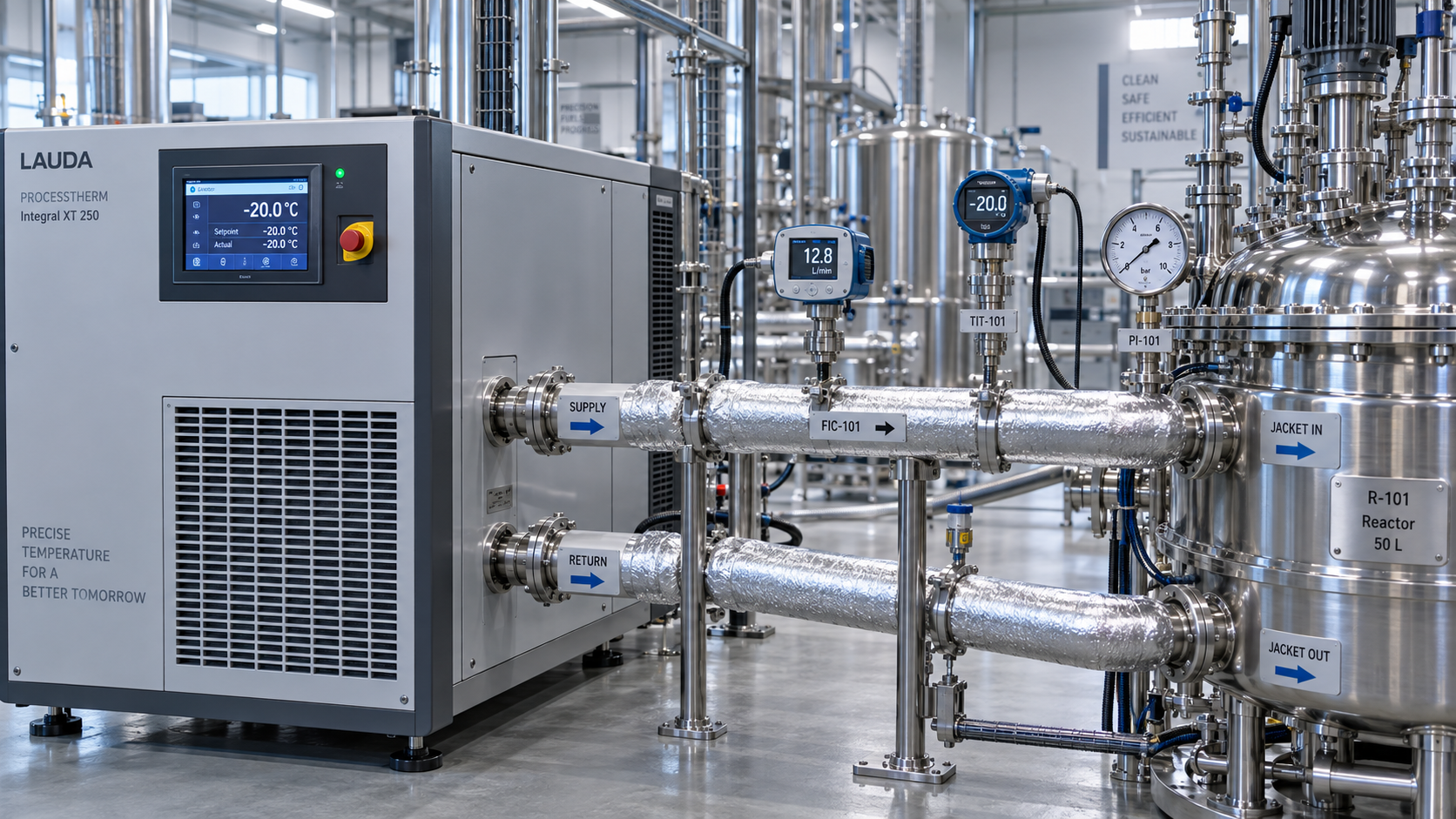
The required coolant supply temperature has a strong effect on cooling energy. Producing colder water generally requires more compressor lift or reduces the ability to use ambient heat rejection. Before fixing the setpoint, distinguish between the temperature needed at the process connection and the temperature leaving the central plant. Pressure drop, pipe heat gain, mixing at bypasses, and control-valve behavior can create a meaningful difference between those two locations.
A process requiring tight control does not always require the entire plant loop to run at the tightest temperature. Sensitive equipment may need a local secondary loop, a trim chiller, or a controlled heat exchanger, while less sensitive users can accept warmer water. This arrangement can permit a higher primary supply temperature and lower central cooling energy. It is appropriate only when isolation, fluid compatibility, and maintenance access are addressed; adding a secondary circuit without a clear control purpose introduces another heat-transfer approach and another pumping load.
The leaving-water temperature should also be judged against the actual heat-transfer surface. A jacket, plate heat exchanger, coil, or mold channel needs a temperature difference between the coolant and the process fluid. Fouling, scaling, low internal velocity, entrained air, and partial blockage reduce the effective heat-transfer coefficient. Lowering the chiller setpoint may conceal these defects temporarily while increasing energy use. When a process once performed well at a warmer supply temperature, inspect the heat-transfer path before resizing the refrigeration plant.
Choose the heat-rejection path for the site conditions
Cooling capacity is rated at stated entering conditions. The site design condition may be warmer, more humid, dustier, or less favorable than the rating basis. Air-cooled condensers respond mainly to dry-bulb temperature and recirculation of discharge air. Evaporative and water-cooled systems are governed more closely by wet-bulb conditions, tower approach, water treatment, and condenser-water temperature. Dry coolers and adiabatic coolers have their own trade between water use, fan energy, and ambient capability.
For outdoor equipment, verify available footprint and airflow geometry before capacity is finalized. Condenser banks placed in narrow yards, beside walls, below overhangs, or near exhaust streams can ingest warmed air. The resulting loss of capacity may appear as a refrigeration problem even when the chiller itself is correctly selected. Snow accumulation, wind exposure, coil fouling, corrosive atmospheres, and roof structural limits can also affect the practical selection.
Where the process can accept a warmer coolant temperature during a portion of the year, waterside or airside economization deserves evaluation. The useful question is not whether free cooling is available in principle. It is whether it can provide the required supply temperature at the required load after accounting for heat-exchanger approach, pump heat, glycol concentration, and control stability. A partial economizer mode can still reduce compressor run time, but its valves and sequence must avoid oscillation between mechanical and free-cooling operation.
Part-load behavior often matters more than peak efficiency
Many process cooling systems spend far more hours below maximum load than at the design peak. A selection based only on full-load efficiency can therefore produce a high annual energy bill. Review performance at the expected combinations of cooling load and ambient temperature, especially the operating band created by normal production. Variable-speed compressors, fans, and pumps can reduce energy when controls permit stable turndown, but their benefit depends on matching the equipment range to the actual profile.
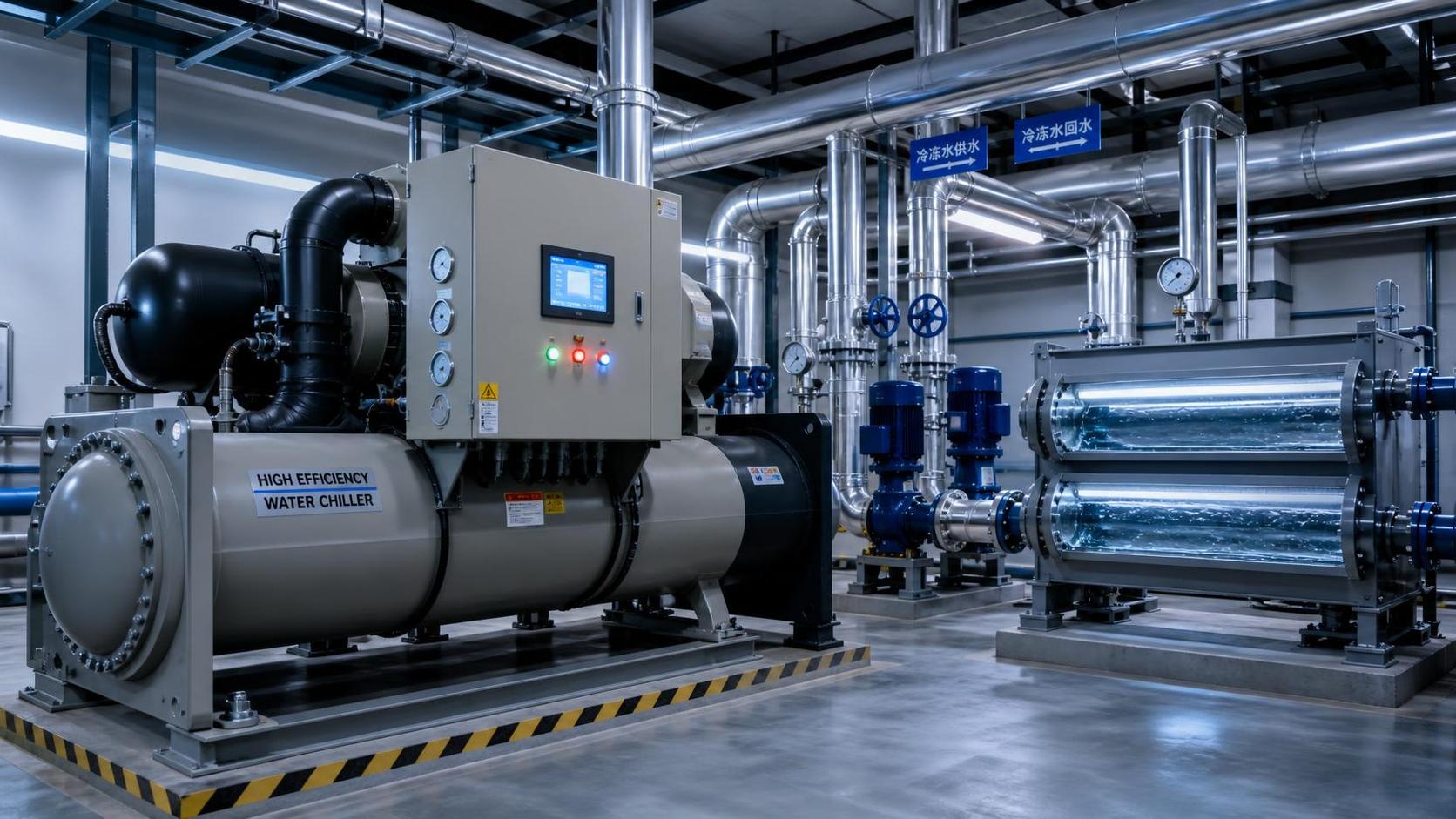
Multiple smaller refrigeration circuits can track a variable load more effectively than one large fixed-capacity circuit. They also create useful maintenance flexibility. Yet excessive modularity adds pumps, controls, valves, heat-exchanger losses, and standby electrical consumption. The right number of modules follows the load shape, required minimum turndown, maintenance philosophy, and consequence of losing one circuit. A system with two equal chillers is not automatically resilient if one remaining unit cannot support the essential process duty during the hottest expected condition.
Variable-primary-flow arrangements need particular care. Reducing flow lowers pump power, but every chiller, heat exchanger, and process branch has a minimum flow or velocity requirement. Poorly located differential-pressure sensors, uncontrolled bypasses, or two-way valves with insufficient authority can cause low delta-T operation. The plant then circulates more water than expected, raising pump energy and reducing available chiller capacity because return water is cooler than the design condition. A low temperature difference is a system diagnosis, not merely a flow adjustment.
Size the distribution system as part of the cooling plant
Pipe diameter, insulation, pump head, fluid selection, and hydraulic separation can change both energy use and temperature control. Undersized pipe raises friction losses and can force a larger pump. Oversized pipe reduces friction but increases cost, fluid volume, and sometimes response time. Select a reasonable velocity range while considering erosion, noise, suspended solids, and the need to carry air toward separators. Long branches should be balanced so that nearby users do not consume flow intended for remote equipment.
Insulate chilled piping wherever uncontrolled heat gain, condensation, or personnel exposure is possible. The vapor barrier deserves the same attention as insulation thickness. A damaged or discontinuous barrier allows moisture to enter the insulation, degrading thermal performance and creating concealed corrosion risk on metal pipe. For low-temperature loops, specify compatible insulation, joint sealing, support inserts, and drainable routing before installation rather than treating them as finishing details.
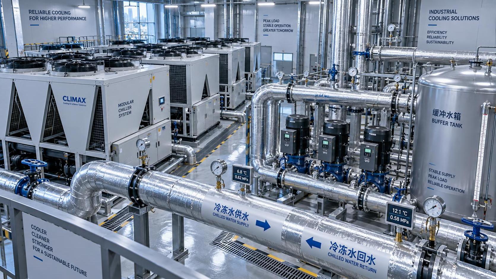
Buffer volume is useful when the refrigeration capacity cannot turn down as quickly as the process load changes. It can limit rapid compressor cycling and smooth short thermal pulses. It does not create continuous capacity, and it should not be used to mask a chiller that is undersized for a sustained load. Calculate its required volume from the mismatch between load and available cooling capacity, the acceptable temperature excursion, and the duration of the disturbance.
Define redundancy by production consequence
Redundancy should be assigned to the load that must remain cooled, not to the total installed load by default. Some equipment can coast down, pause safely, or tolerate a wider temperature band. Other equipment requires uninterrupted cooling to protect product quality, prevent equipment damage, or maintain a controlled process state. Separate essential and nonessential branches where feasible, then verify that the remaining equipment, electrical supply, pumps, controls, and heat-rejection path can support the essential duty under the relevant ambient condition.
A redundant chiller does little good when there is one shared starter panel, one undersized header, a single cooling-tower cell with no isolation, or a control sequence that cannot recognize a failed sensor. Maintenance isolation valves, strainers, air vents, drain points, electrical segregation, and physical access are part of availability. The design should permit cleaning a heat exchanger, replacing a pump seal, or isolating one module without draining the entire process loop.
Validate the selection with a stated operating matrix
Request performance data at the actual process supply temperature, return temperature, fluid concentration, design ambient condition, and expected part-load points. A broad catalog capacity range is insufficient for final sizing. Confirm whether reported electrical input includes compressor, condenser fans, evaporator pumps, tower fans, condenser-water pumps, and any auxiliary heater or trace load. Comparing only the chiller compressor power can misrepresent the energy of the complete cooling system.
The operating matrix should also state allowable supply-temperature deviation, pull-down duty after a warm start, minimum load, maximum flow, pressure-drop allowance, and water-quality assumptions. These values expose conflicts early. For example, a low pressure-drop allowance may require a larger heat exchanger, while a narrow temperature band may require more responsive controls and a more stable hydraulic layout. Neither issue is solved reliably by adding nominal refrigeration tonnage.
Commissioning should test the sequence rather than only proving that equipment starts. Trend supply and return temperatures, flow, compressor loading, fan speed, pump speed, valve positions, ambient conditions, and electrical demand across representative operating states. Compare measured temperature difference with the design basis. When performance deviates, determine whether the cause is reduced heat transfer, excessive flow, inadequate heat rejection, sensor error, control hunting, or a process load outside the original profile. That distinction prevents an expensive but ineffective capacity increase.
A well-sized system leaves a traceable connection between process duty, temperature requirements, ambient conditions, hydraulics, and control behavior. That traceability is what allows capacity to be selected with enough margin for credible uncertainty while avoiding permanent energy waste from equipment sized for a condition the plant rarely experiences.
Related News
- How to size energy efficient industrial cooling for a process loadAuthor :Cryogenic Systems Expert

- How to specify high-precision temperature control in EuropeAuthor :Cryogenic Systems Expert

- How cooling system design affects cleanroom contamination controlAuthor :Cryogenic Systems Expert

- When does industrial cooling heat recovery pay back in energy savings?Author :Cryogenic Systems Expert

- How to size an industrial cooling system for peak process loadsAuthor :Cryogenic Systems Expert

- When are aluminum electronics cooling solutions suitable for high-density designs?Author :Cryogenic Systems Expert

- A thermal management guide for preventing chiller capacity lossAuthor :Cryogenic Systems Expert

- When does aluminum make sense for electronics cooling solutions?Author :Cryogenic Systems Expert

- EU Battery Carbon Footprint Labels Become Mandatory on Aug 18 for Battery-Integrated Cooling and Energy Storage ExportsAuthor :Cryogenic Systems Expert

- China-UAE Direct Sea Route Cuts Lead Times for Industrial Cooling and Compression ExportsAuthor :Cryogenic Systems Expert

- EPA Rule Takes Effect for R-410A Equipment ImportsAuthor :Cryogenic Systems Expert

- EN 378-1:2026 Tightens EU Export ChecksAuthor :Cryogenic Systems Expert

- How to Compare Semiconductor Cooling Solutions by Heat Load and Uptime RiskAuthor :Cryogenic Systems Expert

- EU Label Deadline Hits China Chiller ExportsAuthor :Cryogenic Systems Expert

- How Smart Thermal Systems Improve Industrial Cooling EfficiencyAuthor :Cryogenic Systems Expert

- How to Choose Process Cooling Equipment for Stable Temperature ControlAuthor :Cryogenic Systems Expert

- EU Finalizes 2026 HFC Quota Cut for R-134a ChillersAuthor :Cryogenic Systems Expert

- EU Tightens HFC-134a Quotas for Industrial ChillersAuthor :Cryogenic Systems Expert

- REACH SVHC Update Pressures HFC-134a Chiller Supply ChainsAuthor :Cryogenic Systems Expert

- EU PFAS Coolant Ban Reshapes Chiller ExportsAuthor :Cryogenic Systems Expert

- EU REACH Restricts PFAS Cooling Media ImportsAuthor :Cryogenic Systems Expert

- EU Ecodesign Rule Takes Effect for Industrial ChillersAuthor :Cryogenic Systems Expert

- EU REACH Rule Takes Effect for PFAS in Industrial Cooling ExportsAuthor :Cryogenic Systems Expert

- Industrial Cooling for Plastic Processing: How to Size for Stable Cycle TimesAuthor :Cryogenic Systems Expert

- EU F-Gas Update Bars R404A/R507 in Commercial CoolingAuthor :Cryogenic Systems Expert

- DOE Raises Chiller Efficiency Standard From October 2026Author :Cryogenic Systems Expert

- India Mandates BIS Energy Certification for Industrial ChillersAuthor :Cryogenic Systems Expert

- Energy-Efficient Heat Exchange for Process Cooling: Cost vs PaybackAuthor :Cryogenic Systems Expert

- EPA R-134a Import Ban Takes Effect on July 13, 2026Author :Cryogenic Systems Expert

- India BIS Rule Takes Effect for Industrial ChillersAuthor :Cryogenic Systems Expert

- EPA Cuts R134a Import Quotas 20% From July 10Author :Cryogenic Systems Expert

- How to Compare Energy-Efficient Cooling Systems for Factory Expansion ProjectsAuthor :Cryogenic Systems Expert

- Chiller Price Index Rises 11.3% in Q2Author :Cryogenic Systems Expert

- Saudi SASO Tightens Chiller Import Compliance From July 10Author :Cryogenic Systems Expert

- Dubai Opens Fast-Track Chiller TendersAuthor :Cryogenic Systems Expert

- Japan Raises Chiller COP Floor to 6.2 From Sept. 1Author :Cryogenic Systems Expert
![]()