


How to size a chiller for pharmaceutical cleanroom temperature control




How to size a chiller for pharmaceutical cleanroom temperature control
Sizing a chiller for pharmaceutical cleanroom temperature control requires more than matching nominal cooling capacity to floor area. Process heat, outdoor-air treatment, dehumidification, fan energy, and chilled-water temperatures all affect the selection. Undersizing can compromise environmental stability; excessive capacity can create cycling and control problems without improving protection.
The useful question is not simply “How many kilowatts do we need?” It is “How much cooling must remain available, at what water temperature, under which operating and failure conditions?” That distinction turns a preliminary load estimate into a defensible equipment selection.
Define the environmental duty before calculating capacity
Start with the user requirements specification and the intended operating states. Record room temperature and humidity limits, allowable excursions, production schedules, occupancy, outdoor-air requirements, and recovery expectations after shutdown or cleaning. A room setpoint alone does not describe the cooling duty.
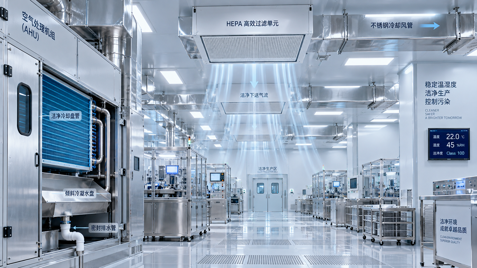
Cleanroom classification is not a direct chiller-sizing input. It informs contamination-control design, which influences airflow, filtration, and system configuration. The cooling calculation still needs actual supply-air volumes, outdoor-air fractions, equipment loads, and coil conditions. Two rooms with the same cleanliness classification can have very different thermal requirements.
Separate the operating scenarios rather than hiding them inside one safety factor:
- Normal production at the relevant outdoor design conditions.
- Low-occupancy operation with ventilation and pressure relationships maintained.
- Cleaning or moisture-intensive activities, where applicable.
- Planned maintenance or loss of one cooling component.
- Restart and recovery, if a defined recovery time is required.
These scenarios need not produce the same peak. The highest sensible load may occur during production, while the lowest required coil temperature may be driven by humid outdoor conditions.
Build the load at the cooling coils—not from floor area
For pharmaceutical temperature control, cleanroom cooling loads should be traced through the air-handling and process systems to the chilled-water plant. Floor-area allowances may support an early feasibility check, but they are too blunt for final selection.
Include envelope gains, lighting, people, process equipment, outdoor air, infiltration where relevant, and fan heat reaching the cooling stream. Use operating heat rejection from equipment suppliers where available. Electrical nameplate input is not automatically the room heat gain: some energy may leave through exhaust, product, drains, or a separate cooling circuit.
Keep direct process cooling separate from room heat. If a machine rejects heat into chilled water, count that load at the plant. If its enclosure also releases heat into the room, include that separate contribution at the air-handling coil. Counting the full electrical input in both places overstates demand.
For an air-side coil, total cooling duty can be calculated from:
Q = ṁda × (hentering − hleaving)
Here, Q is in kW, dry-air mass flow is in kg/s, and moist-air enthalpy is in kJ/kg of dry air. Use the actual mixed-air condition entering the coil. Where outdoor air is treated by a dedicated unit, calculate that unit and downstream recirculation coils separately to avoid counting the outdoor-air load twice.
Be equally careful with cleanroom airflow. A large recirculation volume does not mean the entire airflow carries outdoor design enthalpy. It does, however, affect fan heat, coil selection, and the supply-air temperature needed to remove room sensible heat.
Let dehumidification establish the cold-water requirement
A common selection error is calculating the correct load and then specifying chilled water too warm for moisture removal. Room relative humidity depends on both moisture content and temperature. Maintaining temperature alone does not demonstrate humidity control.
Work backward from the required room moisture condition and moisture gains to the necessary supply-air humidity ratio. Then select the cooling coil using realistic entering-air conditions, face velocity, water flow, and heat-transfer performance. Coil bypass and the approach between water and leaving air matter; chilled-water supply temperature is not the same as leaving-air dew point.
Where air must be cooled below the desired supply temperature to remove moisture, reheat may be needed. Do not simply add the reheat output to an already calculated total coil duty. The cooling calculation should already reflect the lower, dehumidifying leaving-air condition. Reheat is a separate heating requirement, although simultaneous cooling and heating materially affect energy consumption.
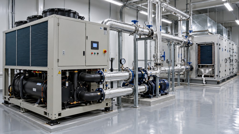
This is also where separate temperature loops deserve consideration. A process circuit or sensible-only load may accept warmer water than a dehumidifying coil. Running every load at the coldest required temperature simplifies distribution, but can impose an avoidable compressor-energy penalty. Separate loops introduce additional equipment and controls, so the decision should follow the load profile rather than a general preference.
Turn the load schedule into a plant capacity
Sum loads that can genuinely coincide. Any diversity allowance should be supported by production schedules, equipment interlocks, or other documented operating constraints. “They probably will not all run together” is not a reliable design basis for a critical environment.
The following example is illustrative only; it is not a benchmark for pharmaceutical facilities.
If the project explicitly adopts a 10% design allowance, the selection duty becomes 770 kW. That percentage is an example, not a recommended universal margin. Identify what each allowance covers: uncertainty, future expansion, fouling, and standby capacity are different issues. Stacking them without explanation can produce a substantially oversized plant.
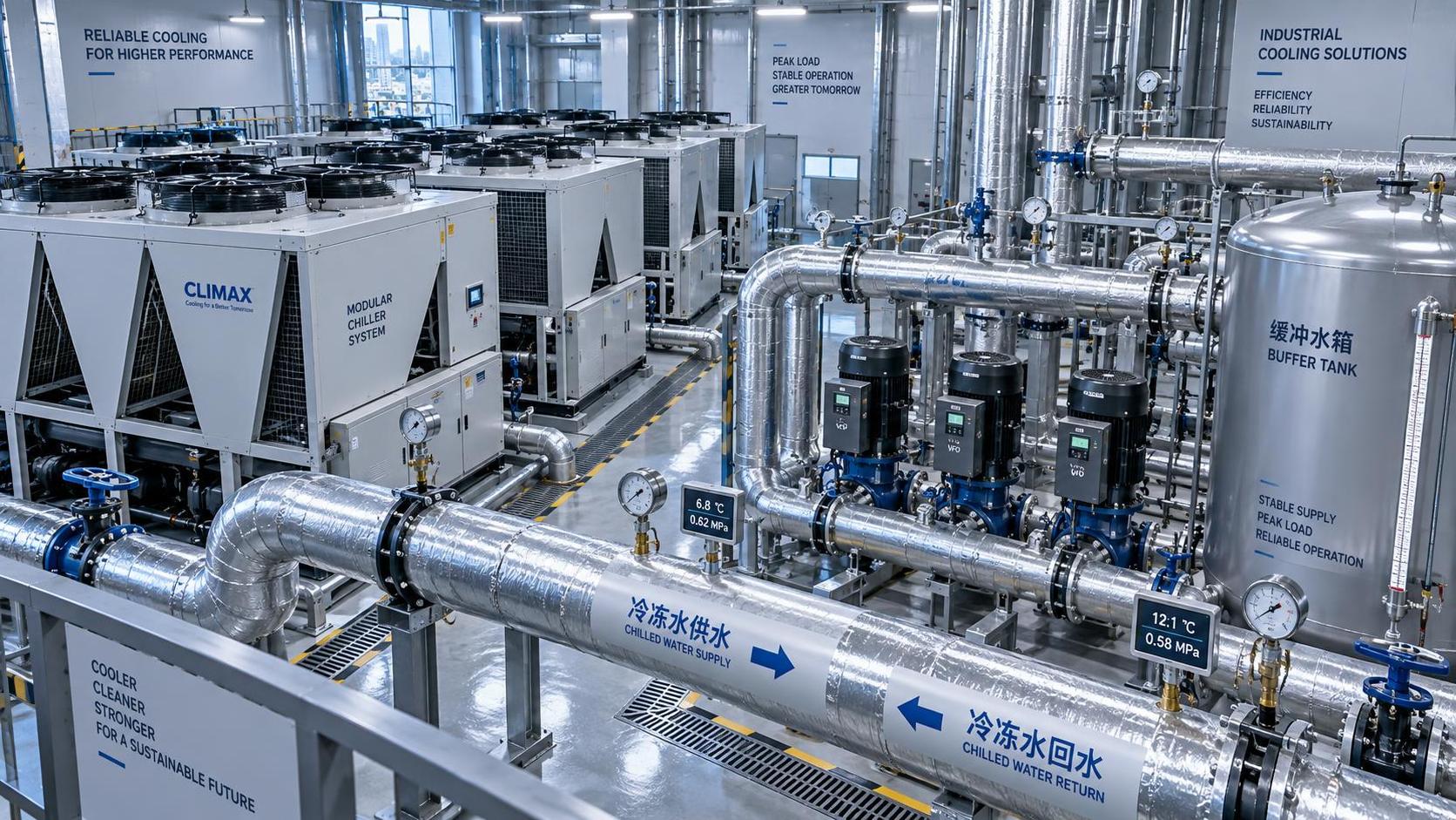
Check water flow independently using Q = ṁ × cp × ΔT. With water approximated at 4.18 kJ/kg·K, 770 kW at a 5 K temperature difference requires about 36.8 kg/s, or approximately 132 m³/h. Glycol mixtures require their actual properties and corresponding equipment corrections.
Do not assume the design temperature difference will occur automatically. Coil valves, bypasses, balancing, and control sequences can produce low return-water temperatures, forcing higher flow and potentially limiting usable plant capacity.
Compare chillers at the conditions they will actually face
Catalogue capacity is a reference point, not a project guarantee. Request a selection at the specified leaving-water temperature, entering-water temperature, flow, fluid concentration, and condenser conditions. For air-cooled equipment, include the site outdoor design condition and installation effects such as hot-air recirculation. For water-cooled equipment, include realistic condenser-water temperatures and cooling-tower performance.
Lower leaving-water temperatures or higher heat-rejection temperatures generally increase compressor lift and can reduce available capacity. A nominally adequate chiller may therefore fail the selection duty once corrected.
At GTC-Matrix, the useful link between thermal-system analysis and compression technology is this operating-point comparison: cooling output, compressor input, and heat rejection must be evaluated together. Comparing purchase prices per nominal kilowatt misses that relationship.
Ask suppliers for both full-load and relevant part-load performance. Include pumps, tower fans where applicable, and reheat in the broader energy assessment. Standardized efficiency ratings help screening, but do not replace a project-specific operating profile.
Specify redundancy and minimum load as separate requirements
Redundancy is not another percentage added to the load. It is a defined capability following a defined failure. If 770 kW must remain available with one chiller unavailable, three units each delivering 400 kW at project conditions would provide 800 kW after losing one unit. Whether that arrangement is appropriate depends on maintenance strategy, load distribution, and the required failure response.
Check the rest of the system before calling it N+1. Shared pumps, power supplies, headers, controls, or heat-rejection equipment may remain single points of failure. Also establish whether standby cooling must be immediate or whether the environmental limits permit a documented restart interval.
At the opposite end, examine the lowest sustained load. Request minimum stable cooling output, minimum evaporator flow, system-volume requirements, and staging behavior. A large plant that cannot run steadily overnight may control worse than a smaller staged arrangement. Buffer storage can reduce cycling or bridge a short transition, but it cannot substitute for sustained cooling capacity.
Make the selection verifiable before purchase
The final comparison should carry a traceable load schedule, psychrometric calculations, coil selections, corrected chiller performance, and a hydraulic and controls basis. Define acceptance conditions for leaving-water stability, load changes, standby changeover, and recovery. Chiller outlet stability alone does not prove room performance; sensor locations, valve authority, airflow, and control-loop interaction also matter.
There is no universal pharmaceutical chiller size, water temperature, or redundancy arrangement. Confirm applicable GMP expectations and site qualification requirements with the responsible quality and engineering teams. Before approving equipment, ask one practical question: can the proposed system maintain the specified environmental conditions at peak moisture load, minimum production load, and the agreed failure condition? Each answer should be supported by calculations and a testable operating sequence.
Ready when you are. Send us a message to get started.
Related News
- How to size a chiller for pharmaceutical cleanroom temperature controlAuthor :Cryogenic Systems Expert

- When do smart thermal systems with sensors reduce chiller energy use?Author :Cryogenic Systems Expert

- Chiller Optimization Checklist for Rising Energy Use and Unstable Cooling OutputAuthor :Cryogenic Systems Expert

- How to Specify a High-Precision Temperature Chiller for Tight-Tolerance ProcessesAuthor :Cryogenic Systems Expert

- Designing Energy-Efficient Industrial Cooling for Variable Process LoadsAuthor :Cryogenic Systems Expert

- Low-GWP Cooling Solutions for Process Plants: Comparing Safety, Efficiency, and CostAuthor :Cryogenic Systems Expert

- How to size energy efficient industrial cooling for a process loadAuthor :Cryogenic Systems Expert

- How to specify high-precision temperature control in EuropeAuthor :Cryogenic Systems Expert

- How cooling system design affects cleanroom contamination controlAuthor :Cryogenic Systems Expert

- When does industrial cooling heat recovery pay back in energy savings?Author :Cryogenic Systems Expert

- How to size an industrial cooling system for peak process loadsAuthor :Cryogenic Systems Expert

- When are aluminum electronics cooling solutions suitable for high-density designs?Author :Cryogenic Systems Expert

- A thermal management guide for preventing chiller capacity lossAuthor :Cryogenic Systems Expert

- When does aluminum make sense for electronics cooling solutions?Author :Cryogenic Systems Expert

- EU Battery Carbon Footprint Labels Become Mandatory on Aug 18 for Battery-Integrated Cooling and Energy Storage ExportsAuthor :Cryogenic Systems Expert

- China-UAE Direct Sea Route Cuts Lead Times for Industrial Cooling and Compression ExportsAuthor :Cryogenic Systems Expert

- EPA Rule Takes Effect for R-410A Equipment ImportsAuthor :Cryogenic Systems Expert

- EN 378-1:2026 Tightens EU Export ChecksAuthor :Cryogenic Systems Expert

- How to Compare Semiconductor Cooling Solutions by Heat Load and Uptime RiskAuthor :Cryogenic Systems Expert

- EU Label Deadline Hits China Chiller ExportsAuthor :Cryogenic Systems Expert

- How Smart Thermal Systems Improve Industrial Cooling EfficiencyAuthor :Cryogenic Systems Expert

- How to Choose Process Cooling Equipment for Stable Temperature ControlAuthor :Cryogenic Systems Expert

- EU Finalizes 2026 HFC Quota Cut for R-134a ChillersAuthor :Cryogenic Systems Expert

- EU Tightens HFC-134a Quotas for Industrial ChillersAuthor :Cryogenic Systems Expert

- REACH SVHC Update Pressures HFC-134a Chiller Supply ChainsAuthor :Cryogenic Systems Expert

- EU PFAS Coolant Ban Reshapes Chiller ExportsAuthor :Cryogenic Systems Expert

- EU REACH Restricts PFAS Cooling Media ImportsAuthor :Cryogenic Systems Expert

- EU Ecodesign Rule Takes Effect for Industrial ChillersAuthor :Cryogenic Systems Expert

- EU REACH Rule Takes Effect for PFAS in Industrial Cooling ExportsAuthor :Cryogenic Systems Expert

- Industrial Cooling for Plastic Processing: How to Size for Stable Cycle TimesAuthor :Cryogenic Systems Expert

- EU F-Gas Update Bars R404A/R507 in Commercial CoolingAuthor :Cryogenic Systems Expert

- DOE Raises Chiller Efficiency Standard From October 2026Author :Cryogenic Systems Expert

- India Mandates BIS Energy Certification for Industrial ChillersAuthor :Cryogenic Systems Expert

- Energy-Efficient Heat Exchange for Process Cooling: Cost vs PaybackAuthor :Cryogenic Systems Expert

- EPA R-134a Import Ban Takes Effect on July 13, 2026Author :Cryogenic Systems Expert

- India BIS Rule Takes Effect for Industrial ChillersAuthor :Cryogenic Systems Expert